
Plug assembly with male and female integration, plug combination assembly structure and connector with the same

A technology of plug assembly and combined structure, which is applied in the direction of two-part connection device, connection, parts of connection device, etc., can solve problems such as bite corrosion, reduce plug life, waste, etc., and achieve fast and convenient insertion and extraction, plug-in The effect of increasing the number of pulls and saving operation time

Pending Publication Date: 2018-03-23
SUZHOU LIFA ELECTRONICS
View PDF0 Cites 3 Cited by
  • Summary
  • Abstract
  • Description
  • Claims
  • Application Information

AI Technical Summary

Problems solved by technology

[0003] At present, the self-plugging connector is usually composed of the shell and the connector inside the shell. The internal connector realizes the connection of the two circuits through plugging. The connector is usually molded integrally through a mold. The mating of the male plug and the female plug requires more parts to be formed, so more molds are used, resulting in waste; while the current mating of the male plug and the female plug is usually through the combination of the card and the card slot, which is convenient to combine. When disconnecting, it is usually necessary to manually press the card into the inside to pull it out, which greatly affects the disconnection time, and the card and the card slot are made of the same material, which will cause bite corrosion after long-term use, reducing the Plug-in life; the shell is usually composed of multiple parts, and a gap is formed between two adjacent parts. After installation, the hand feel is poor, and it is not suitable for the use of high-end electronic products.

Method used


Image

  • Plug assembly with male and female integration, plug combination assembly structure and connector with the same
  • Plug assembly with male and female integration, plug combination assembly structure and connector with the same
  • Plug assembly with male and female integration, plug combination assembly structure and connector with the same

Examples


Embodiment Construction

[0033] The present invention will be described in detail below in conjunction with the accompanying drawings.

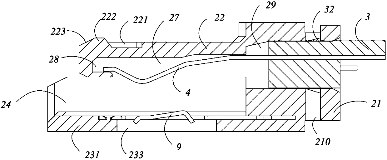
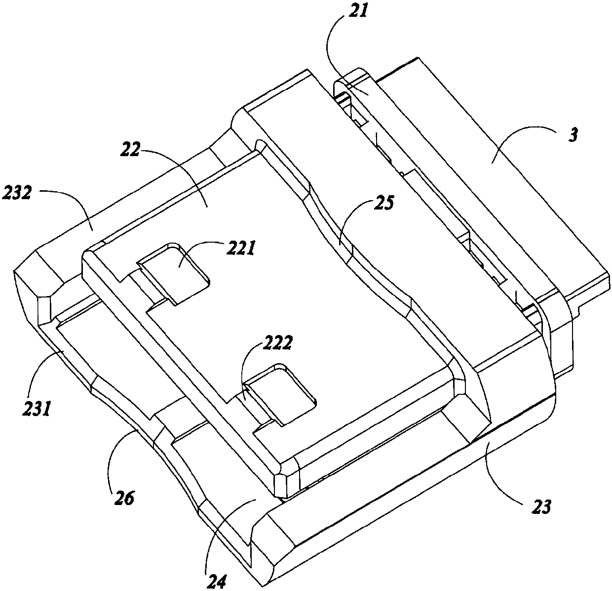
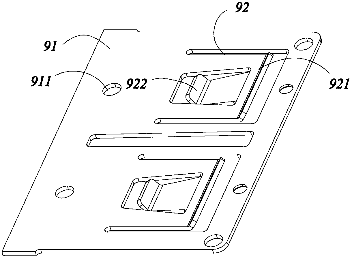
[0034] Such as figure 1 and figure 2 A male-female plug assembly is shown, including a separate plug 2, a terminal positioning block 3 located on the plug 2, and a metal sheet 4 for conducting electricity inserted into the plug 2 through the terminal positioning block 3. The plug 2 includes a base 21, a guide 22 protruding upward from the base 21, and a positioning member 23, and an insertion cavity 24 is formed between the guide 22 and the positioning member 23; the positioning member 23 includes a base plate 231 and a The side plates 232 extending upward on both sides, the insertion cavity 24 is formed between the two side plates 232, the bottom plate 231 and the guide 22; The spring leaf 9 is provided with a positioning groove 221 on the side away from the insertion cavity 24 on the guide member 22; The positioning groove 221 of the plug 2 is matched; the spri...


PUM


Abstract

The invention relates to a plug assembly with male and female integration, a plug combination assembly structure and a connector with the same. The plug assembly comprises a plug arranged in a split manner, a terminal positioning block arranged on the plug, and a metal piece that is inserted into the plug by the terminal positioning block and is used for electric conduction. The plug consists of apedestal, a guiding element and a positioning element, wherein the guiding element and the positioning element extend upwardly from the pedestal; an insertion cavity is formed between the guiding element and the positioning element; a spring piece is arranged at the positioning element arranged inside the insertion cavity; and a positioning groove is formed in one side, far away from the insertion cavity, of the guiding element. According to the split plug assembly, welding, combined installation, and damaged part replacement are carried out conveniently. When the two plug assemblies with thestructures are buckled mutually, dies for investment is reduced by half; and after cooperation of the two plug assemblies, plugging in and pulling out are carried out rapidly and conveniently. On thebasis of cooperation of the spring piece with the positioning groove, the appearance of the product does not change after multiple times of plugging, so that the plugging times is increased obviously.

Description

technical field [0001] The invention relates to the technical field of electronic connectors, in particular to a hermaphrodite plug assembly, a plug combination structure and a connector having the same. Background technique [0002] Electronic connectors (also often referred to as circuit connectors, electrical connectors) bridge two conductors on a circuit so that current or signals can flow from one conductor to another conductor. The self-plugging connector is a kind of electronic connector. [0003] At present, the self-plugging connector is usually composed of the shell and the connector inside the shell. The internal connector realizes the connection of the two circuits through plugging. The connector is usually molded integrally through a mold. The mating of the male plug and the female plug requires more parts to be formed, so more molds are used, resulting in waste; while the current mating of the male plug and the female plug is usually through the combination of...

Claims


Application Information

Patent Timeline
IPC IPC(8): H01R13/502H01R13/627H01R13/631H01R24/84
CPCH01R13/502H01R13/6275H01R13/631H01R24/84
Inventor 程卫亚杨国梁徐思雷汪祖民
Owner SUZHOU LIFA ELECTRONICS
Learn More