
Outer rotor brushless motor

A brushless motor and outer rotor technology, applied in electrical components, electromechanical devices, electric components, etc., can solve the problems of affecting the heat dissipation effect, polluting the bearings, low protection level, etc., to speed up the heat dissipation efficiency, improve the protection level, and prolong the use. effect of life

Pending Publication Date: 2018-03-23
惠州市精电动力科技有限公司
View PDF7 Cites 4 Cited by
  • Summary
  • Abstract
  • Description
  • Claims
  • Application Information

AI Technical Summary

Problems solved by technology

The current method is to hollow out the two ends of the motor, so as to promote the circulation of air inside and outside, which can strengthen the heat dissipation, but this structure will make it easy for foreign matter to enter the motor from the hollow, pollute the bearing, and the IP protection level is not high
In order to prevent foreign matter from entering the motor, the two ends of the motor are closed, which will affect the heat dissipation effect
That is to say, the existing motor cannot have both high IP protection level and heat dissipation function at the same time

Method used


Image

  • Outer rotor brushless motor
  • Outer rotor brushless motor
  • Outer rotor brushless motor

Examples


Embodiment Construction

[0021] A number of embodiments of the present invention will be disclosed in the following figures. For the sake of clarity, many practical details will be described together in the following description. It should be understood, however, that these practical details should not be used to limit the invention. That is, in some embodiments of the invention, these practical details are not necessary. In addition, for the sake of simplifying the drawings, some well-known and commonly used structures and components will be shown in a simple schematic manner in the drawings.

[0022] It should be noted that all directional indications (such as up, down, left, right, front, back...) in the embodiments of the present invention are only used to explain the relationship between the components in a certain posture (as shown in the accompanying drawings). Relative positional relationship, movement conditions, etc., if the specific posture changes, the directional indication also changes ...


PUM


Abstract

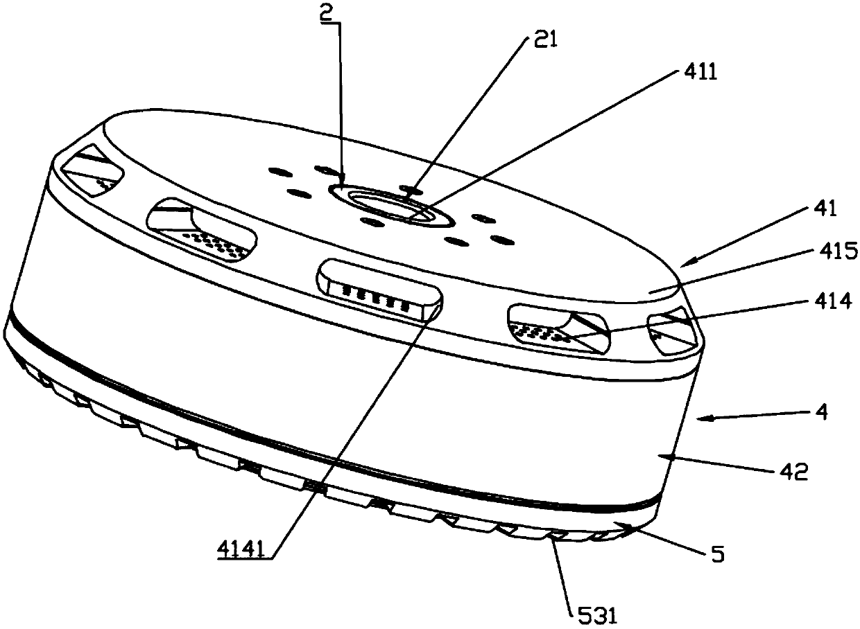
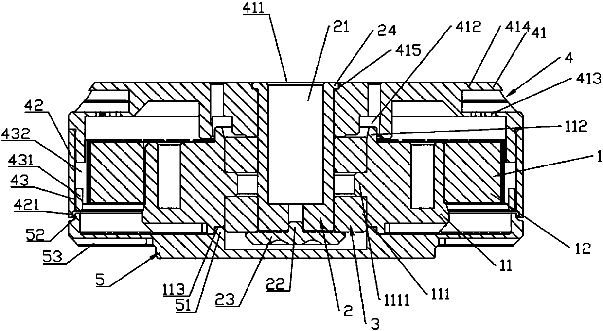
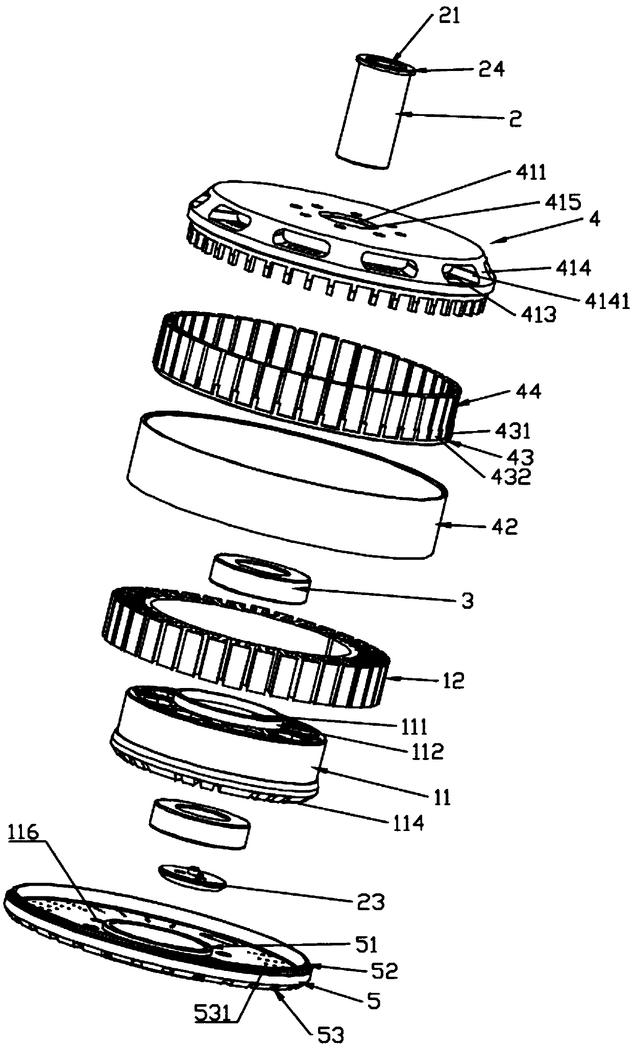
The invention discloses an outer rotor brushless motor, which comprises a stator assembly, a motor shaft, a plurality of bearings, a rotor assembly and an end cover. The stator assembly is provided with a first annular boss, and an annular concave groove is arranged on the other side of the stator assembly. An annular convex groove is formed in the inner side of the bottom cover of the rotor assembly, and a first groove is formed in the inner side of the side wall thereof. The annular convex groove corresponds to the first annular boss. A second annular boss is arranged on the inner side of the end face of the end cover and a first boss is arranged on the edge thereof. The second annular boss corresponds to the annular concave groove. The first boss corresponds to the first groove. The bottom cover of the rotor assembly comprises a plurality of sets of first heat dissipation holes and a dust blocking plate. The dust blocking plate comprises a plurality of partition walls. According tothe invention, the connection parts of all components of an external rotor brushless motor disclosed by the invention are realized in the convex-concave butt joint manner, so that external foreign matters can be prevented from entering the motor and influencing the service life of the motor. The IP protection level is improved. Meanwhile, the space is fully utilized on all components to form a heat dissipation structure. The heat dissipation efficiency during operation is accelerated, and the service life is prolonged.

Description

technical field [0001] The invention relates to the technical field of motors, in particular to an outer rotor brushless motor. Background technique [0002] With the promotion of external rotor brushless motors, in some fields that require high IP protection level and heat dissipation, such as model aircraft, unmanned aerial vehicles and other products, the IP protection level and heat dissipation requirements of external rotor brushless motors continue to increase, in order to ensure Reliability of product operation. The current practice is to hollow out both ends of the motor to promote air circulation inside and outside, which can enhance heat dissipation, but this structure will make it easy for foreign matter to enter the motor from the hollow and pollute the bearings, and the IP protection level is not high. In order to prevent foreign matter from entering the motor, the two ends of the motor are closed, which will affect the heat dissipation effect. That is, the ex...

Claims


Application Information

Patent Timeline
Patent Type & Authority Applications(China)
IPC IPC(8): H02K5/20H02K5/04H02K5/10H02K1/32H02K29/00
CPCH02K1/32H02K5/04H02K5/10H02K5/20H02K29/00
Inventor 彭利华
Owner 惠州市精电动力科技有限公司
Learn More