Belt carrier fixing plate

A technology of fixing plates and loops, applied in the directions of ligaments, muscles, etc., can solve the problems of unadjustable length, increase operation time, etc., and achieve the effect of increasing service life, expanding application scope, and increasing contact area.

Pending Publication Date: 2018-03-27
YUNYI BEIJING MEDICAL INSTR CO LTD
View PDF0 Cites 0 Cited by
  • Summary
  • Abstract
  • Description
  • Claims
  • Application Information

AI Technical Summary

Problems solved by technology

However, the structure of the current fixation plate with loops is very simple, only two threading holes are opened on the end surface, and the graft is directly hung with sutures, which will have a cutting effect on the graft
In addition, the length of the suture cannot be adjusted, and the required coil length can only be calculated through measurement, which increases the operation time

Method used


Image

  • Belt carrier fixing plate
  • Belt carrier fixing plate
  • Belt carrier fixing plate

Examples


Embodiment 1

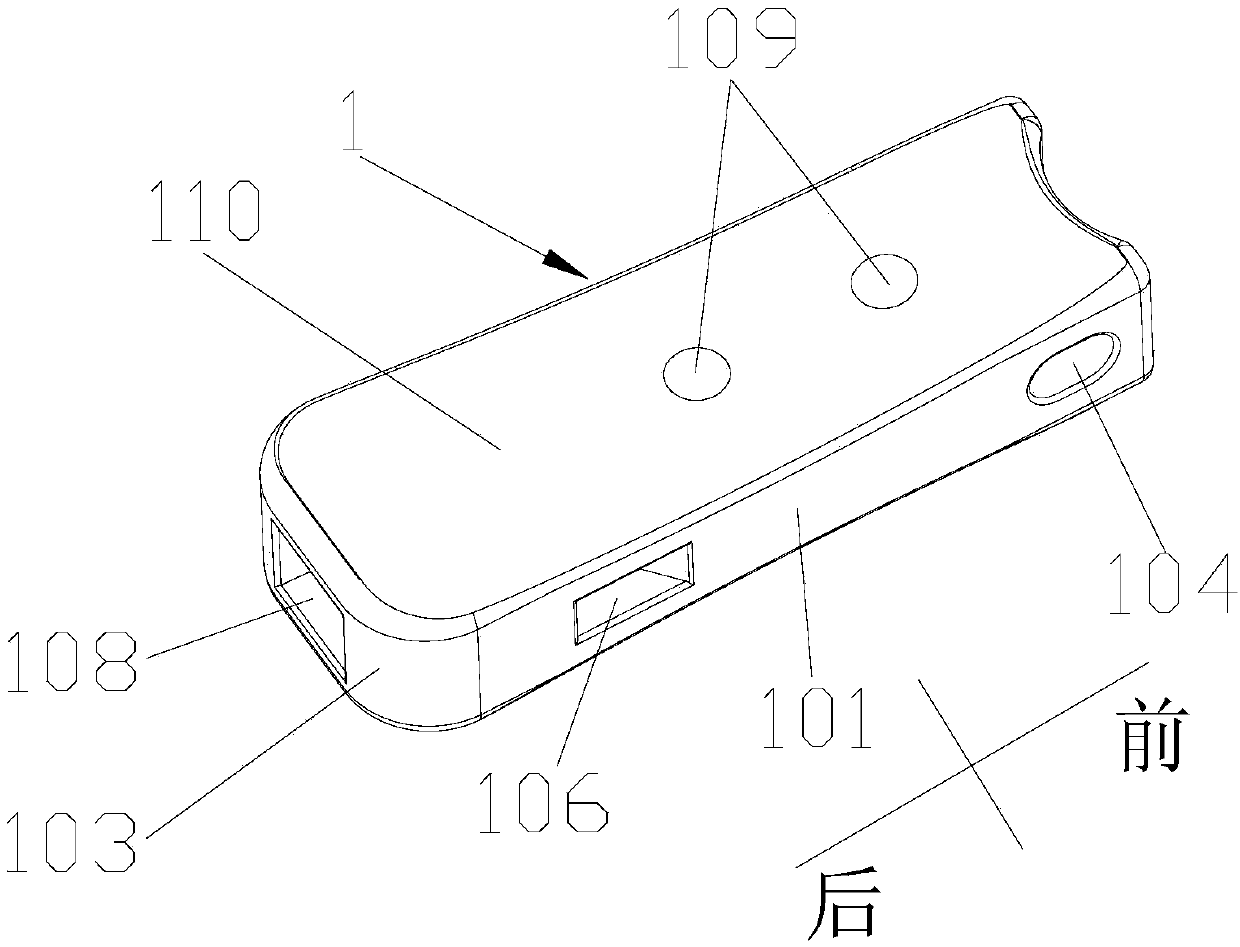
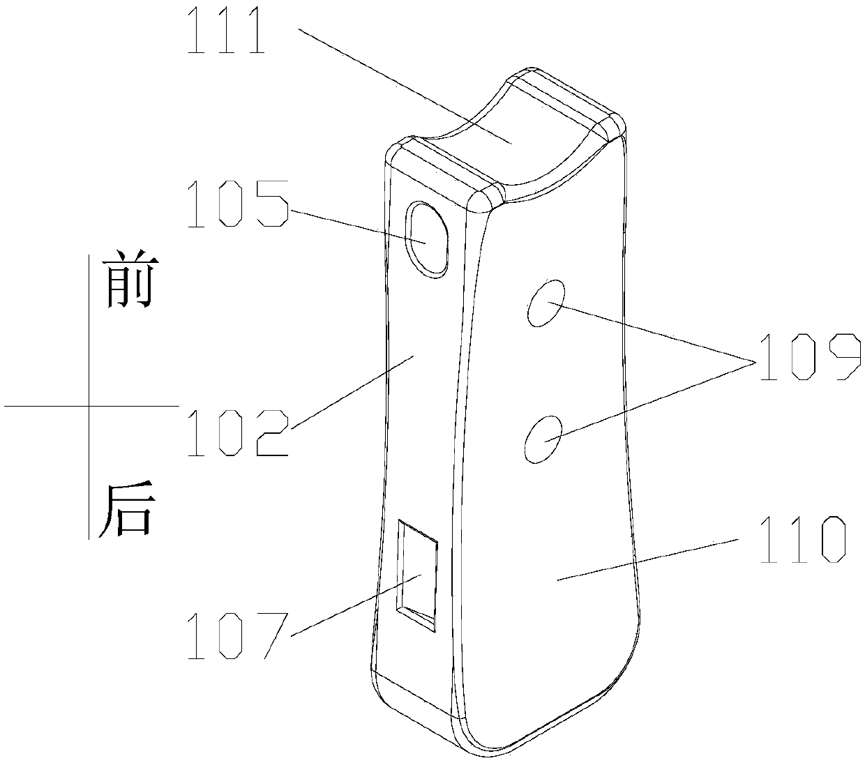
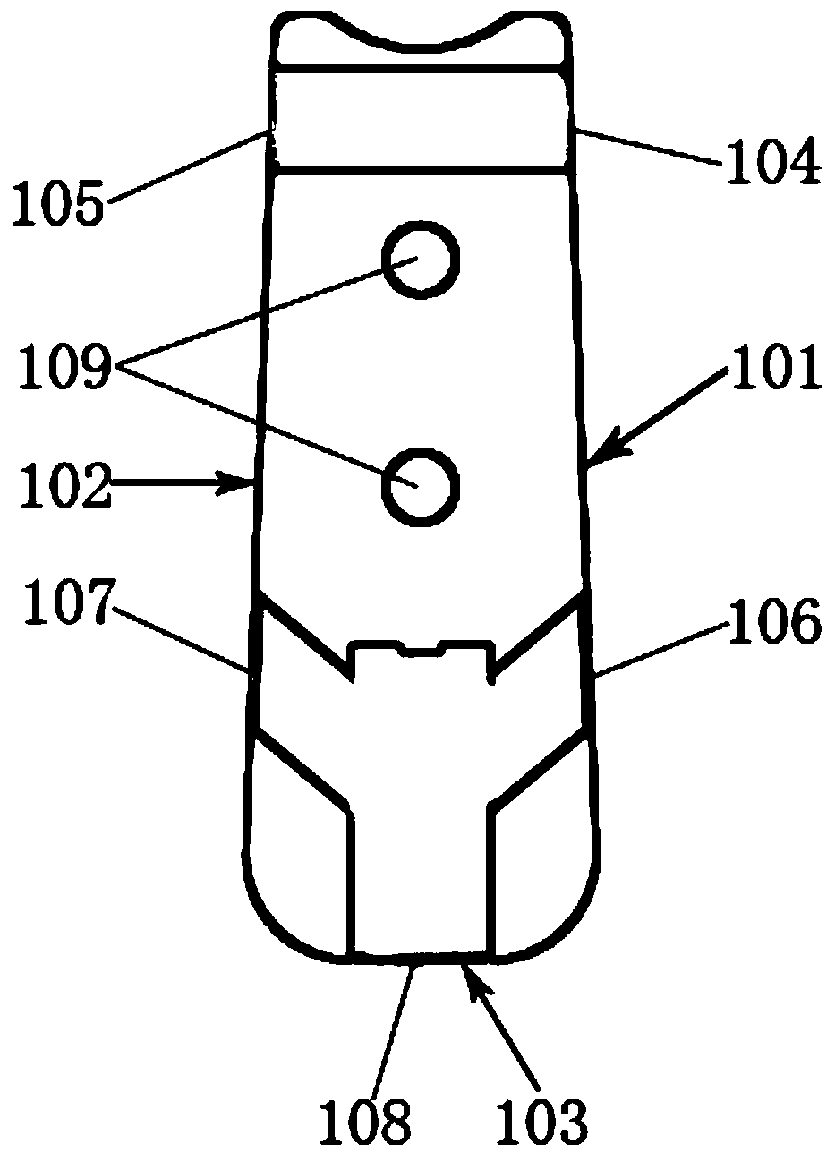
[0023] Embodiment 1 of the present invention: as Figure 1-Figure 5 As shown, a belt loop fixing plate includes a first fixing plate 1 , a second fixing plate 2 and a connecting line 3 , and the first fixing plate 1 and the second fixing plate 2 are connected through the connecting line 3 . Wherein the first side 101 and the second side 102 of the first fixing plate 1 are symmetrically arranged, the front end of the first side 101 is provided with a side hole A1, and the front end of the second side 102 is provided with a side hole A2, so The side hole A1 and the side hole A2 are arranged symmetrically and communicate with each other. A side hole B1 is defined at the rear end of the first side 101 , and a side hole B2 is defined at the rear end of the second side 102 . The side holes B1 and B2 are arranged symmetrically and communicate with each other. The rear end face 103 of the first fixing plate 1 is provided with a rear end face hole 108, the rear end face hole 108 commu...

Embodiment 2

[0025] Embodiment 2: as Figure 1-Figure 5 As shown, a belt loop fixing plate includes a first fixing plate 1 , a second fixing plate 2 and a connecting line 3 , and the first fixing plate 1 and the second fixing plate 2 are connected through the connecting line 3 . Wherein the first side 101 and the second side 102 of the first fixing plate 1 are symmetrically arranged, the front end of the first side 101 is provided with a side hole A1, and the front end of the second side 102 is provided with a side hole A2, so The side hole A1 and the side hole A2 are arranged symmetrically and communicate with each other. A side hole B1 is defined at the rear end of the first side 101 , and a side hole B2 is defined at the rear end of the second side 102 . The side holes B1 and B2 are arranged symmetrically and communicate with each other. The rear end face 103 of the first fixing plate 1 is provided with a rear end face hole 108, the rear end face hole 108 communicates with the side hol...


PUM

PropertyMeasurementUnit
Lengthaaaaaaaaaa
Widthaaaaaaaaaa
Thicknessaaaaaaaaaa

Abstract

The invention discloses a fixing plate, in particular to a belt carrier fixing plate, and belongs to the technical field of rebuilding of cruciate ligaments. The belt carrier fixing plate comprises afirst fixing plate, a second fixing plate and a connecting line; the first fixing plate and the second fixing plate are connected through the connecting line, wherein a first side face and a second side face of the first fixing plate are symmetrical to each other, the front end of the first side face is provided with a side face hole A1; the front end of the second side face is provided with a side face hole A2, the side faced hole A1 and the side face hole A2 are symmetrically arranged and penetrated to each other; the back end of the first side face is provided with a side face hole B1, andthe back end of the second side face is provided with a side face hole B2; the side face hole B1 and the side face hole B2 are symmetrically arranged and penetrated to each other; a back end face holeis arranged on the back end face of the first fixing plate, and the back end face hole is connected with the side face hole B1; the back end face hole is further connected with the side face hole B2.The belt carrier fixing plate has the advantages of effectively increasing contact area with a transplant, reducing the cutting of the transplant by the connecting line, and increasing the service life of the product.

Description

technical field [0001] The invention relates to a fixing plate, in particular to a fixing plate with loops, which belongs to the technical field of cruciate ligament reconstruction. Background technique [0002] Loop plate fixation is an endoscopic technique in ACL reconstruction surgery (ie, cruciate ligament reconstruction). This technique does not require an additional lateral condylar incision, and the upper end of the tendon graft without bone blocks at both ends can be firmly fixed in the femoral bone canal by using a fixed plate with loops. One of the reconstruction techniques without bone grafts. However, the structure of the existing belt-loop fixation plate is very simple, and only two threading holes are provided on the end surface, and the graft is directly suspended with sutures, and the sutures will have a cutting effect on the graft. In addition, the length of the suture cannot be adjusted, and the required coil length can only be calculated through measurem...

Claims


Application Information

Patent Timeline
IPC IPC(8): A61F2/08
CPCA61F2/0811
Inventor 赵学东刘记梅颜博刘继强
Owner YUNYI BEIJING MEDICAL INSTR CO LTD
Why Eureka
Try Eureka