Fertilizer crushing machining device

A processing device and fertilizer technology, which is applied in the direction of solid separation, filter screen, grid, etc., can solve the problems of unfavorable mechanical fertilization, poor crushing effect, and blockage of fertilization nozzles, so as to improve the working efficiency of sieving materials and improve the uniformity of crushing The effect of improving the crushing efficiency

Inactive Publication Date: 2018-03-27
潘荣静
View PDF5 Cites 3 Cited by
  • Summary
  • Abstract
  • Description
  • Claims
  • Application Information

AI Technical Summary

Problems solved by technology

[0002] Due to the strong hygroscopicity of the fertilizer, it is very easy to agglomerate in the air. Large agglomerates will block the feeding port of the hopper, which will bring many difficulties to storage, transportation and use. Serious agglomeration of chemical fertilizers is difficult to break, and some of the fertilizers are agglomerated. Blocks are unfavorable to mechanical fertilization, and it is easy to cause the nozzle head of fertilization to be blocked, which will bring inconvenience to fertilization, and the fertilizer can be fully absorbed by the plants after the fertilizer is crushed. The disadvantage of low efficiency, and the traditional crushing head is prone to wear and tear during long-term use. In addition, because the transmission crushing equipment is relatively expensive, it is not suitable for small-scale farmers.

Method used


Image

  • Fertilizer crushing machining device
  • Fertilizer crushing machining device
  • Fertilizer crushing machining device

Examples


Embodiment Construction

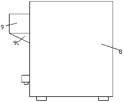
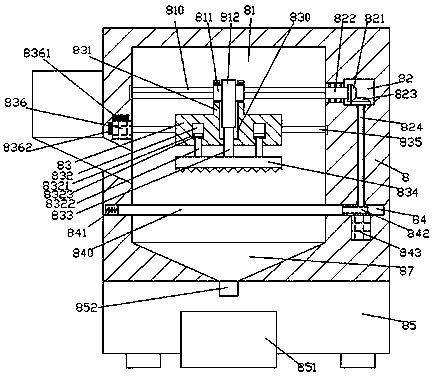
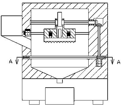
[0019] Such as Figure 1-Figure 4 As shown, a fertilizer crushing and processing device of the present invention includes a processing machine body 8, a first cavity 81 is arranged inside the processing machine body 8, and a funnel extending downwards is connected to the bottom of the first cavity 81. Cavity 87, the first cavity 81 is provided with a mobile bracket 83 that is connected with the front and rear end faces and the front and rear inner walls of the first cavity 81 in a pressure-sliding fit, and the mobile bracket 83 is provided with a screw fit connection and left and right Extended threaded rod 835, grooves 830 are provided in the top end surface of the mobile bracket 83, and support frames 831 extending upwards are fixed at the edges of the left and right sides of the top of the groove 830, and the supports on the left and right sides An inner spline sleeve 811 is rotationally fitted and connected between the frames 831, a first eccentric wheel 812 is fixed on th...


PUM


Abstract

The invention discloses a fertilizer crushing machining device which comprises a machining machine body. A first cavity is formed in the machining machine body. A funnel cavity extending downwards isformed in the bottom of the first cavity in a communicating manner. A moving bracket is arranged in the first cavity, wherein the front end face and the rear end face of the moving bracket are connected with the front inner wall and the rear inner wall of the first cavity in an abutting manner and a sliding fit manner. A thread rod extending left and right is arranged in the moving bracket in a threaded fit connection manner. A groove is formed in the end face of the top of the moving bracket. Supporting frames extending upwards are fixedly arranged on the edges of the left side and the rightside of the top of the groove. An internal spline sleeve is connected between the supporting frames on the left side and the right side in a rotary fit manner. A first eccentric wheel is fixedly arranged on the outer surface of the internal spline sleeve in the circumferential direction. An external spline shaft extending towards the left side and the right side is connected in the internal splinesleeve in a sliding fit manner. The extending tail end of the left side of the external spline shaft and the inner wall of the left side of the first cavity are connected in a rotary fit manner. Thefertilizer crushing machining device is simple in structure and convenient to operate, the crushing efficiency and crushing uniformity are improved, and meanwhile the safety of crushing work is improved.

Description

technical field [0001] The invention relates to the technical field of fertilizer processing, in particular to a fertilizer crushing and processing device. Background technique [0002] Due to the strong hygroscopicity of the fertilizer, it is very easy to agglomerate in the air. Large agglomerates will block the discharge port of the hopper, which will bring many difficulties to storage, transportation and use. The severe agglomeration of chemical fertilizers is difficult to break, and some of the fertilizers are agglomerated. Blocks are unfavorable to mechanical fertilization, and it is easy to cause the nozzle head of fertilization to be blocked, which will bring inconvenience to fertilization, and the fertilizer can only be fully absorbed by plants after the fertilizer is crushed. The disadvantage of low efficiency, and the traditional crushing head is prone to wear and tear during long-term use. In addition, because the transmission crushing equipment is relatively expe...

Claims


Application Information

Patent Timeline
Patent Type & Authority Applications(China)
IPC IPC(8): B02C1/00B02C23/00B02C23/04B02C23/10B07B1/28B07B1/42
CPCB02C1/00B02C23/00B02C23/04B02C23/10B07B1/28B07B1/42
Inventor 潘荣静
Owner 潘荣静
Why Eureka
Try Eureka