Valve machining technology

A processing technology and valve technology, which is applied in the field of valve processing technology, can solve the problems of valve body forming influence, copper water obstruction, large temperature difference, etc., and achieve the effect of slow condensation speed, preventing cracks, and slowing down the heat dissipation speed

Inactive Publication Date: 2018-03-27
ZHENJIANG YIBAO ELECTRICAL TECH CO LTD
View PDF7 Cites 7 Cited by
  • Summary
  • Abstract
  • Description
  • Claims
  • Application Information

AI Technical Summary

Problems solved by technology

[0004] However, in the process of injecting copper water into the mold, since the temperature of the mold is basically the same as that of the working environment, there is a large temperature difference between 10°C to 40°C and the temperatu

Method used


Image

  • Valve machining technology
  • Valve machining technology
  • Valve machining technology

Examples


Embodiment 1

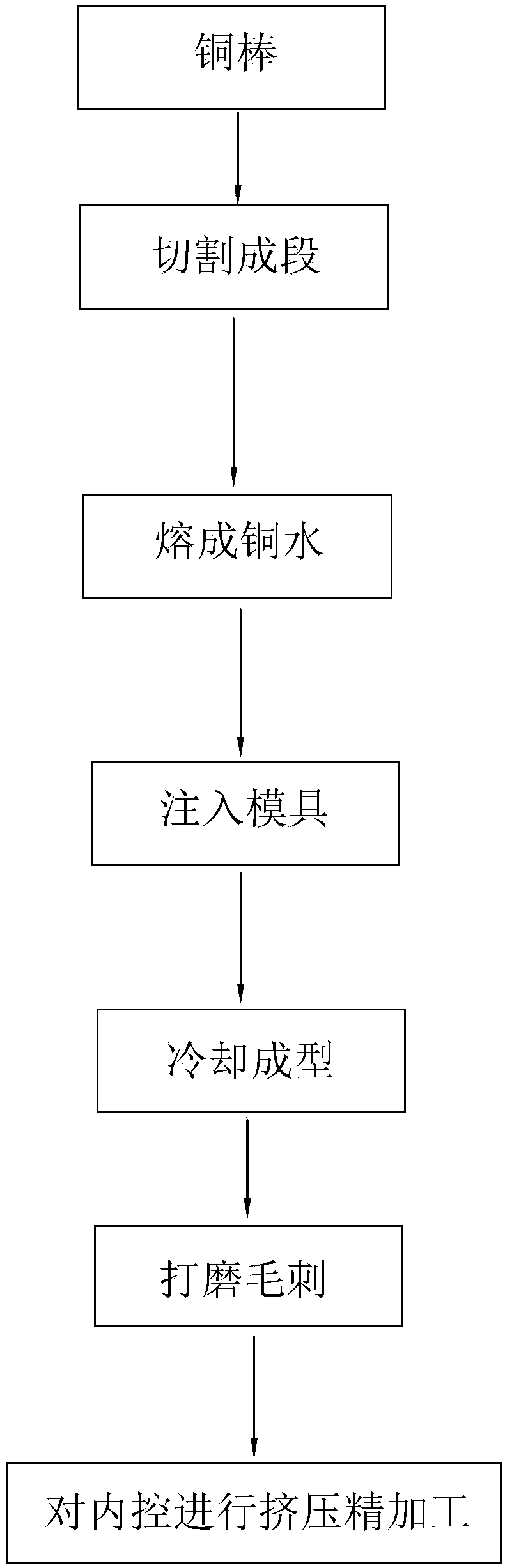
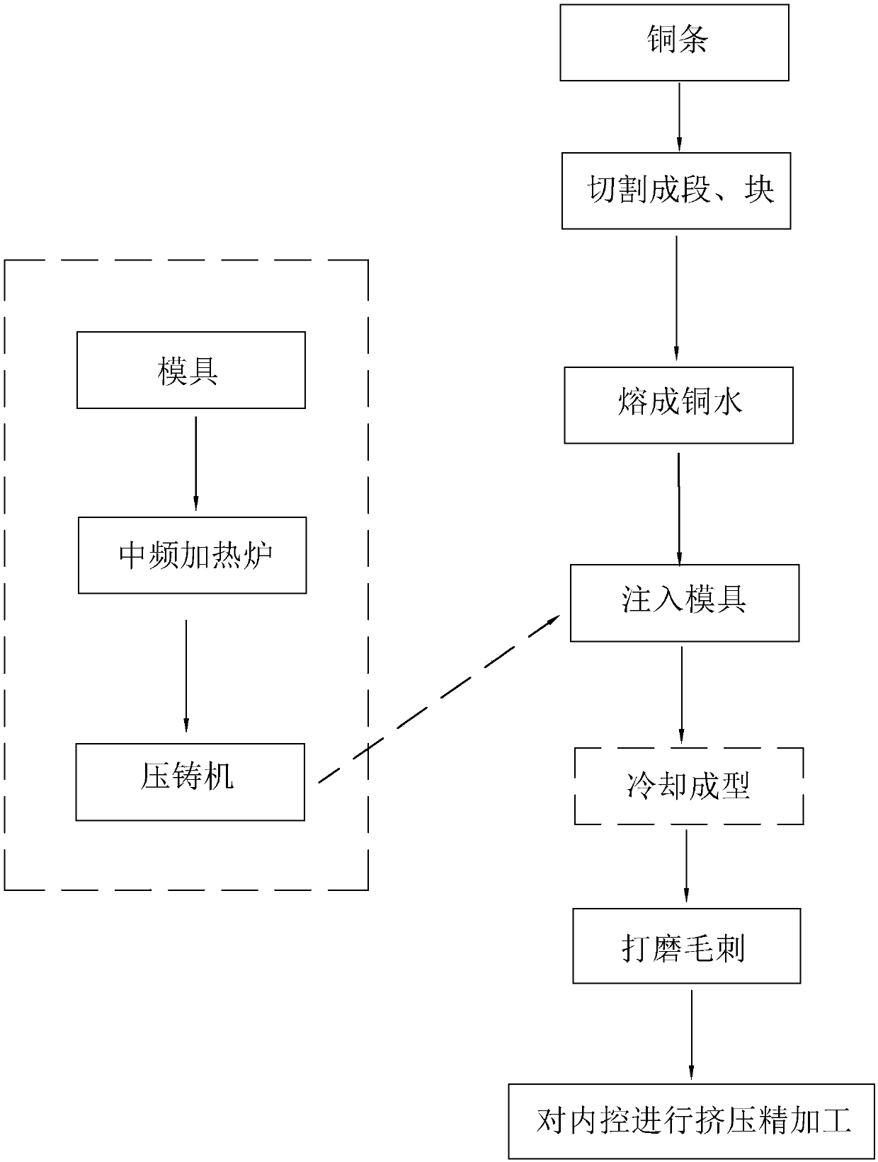
[0042] The processing technology for producing copper globe valve includes the following steps:

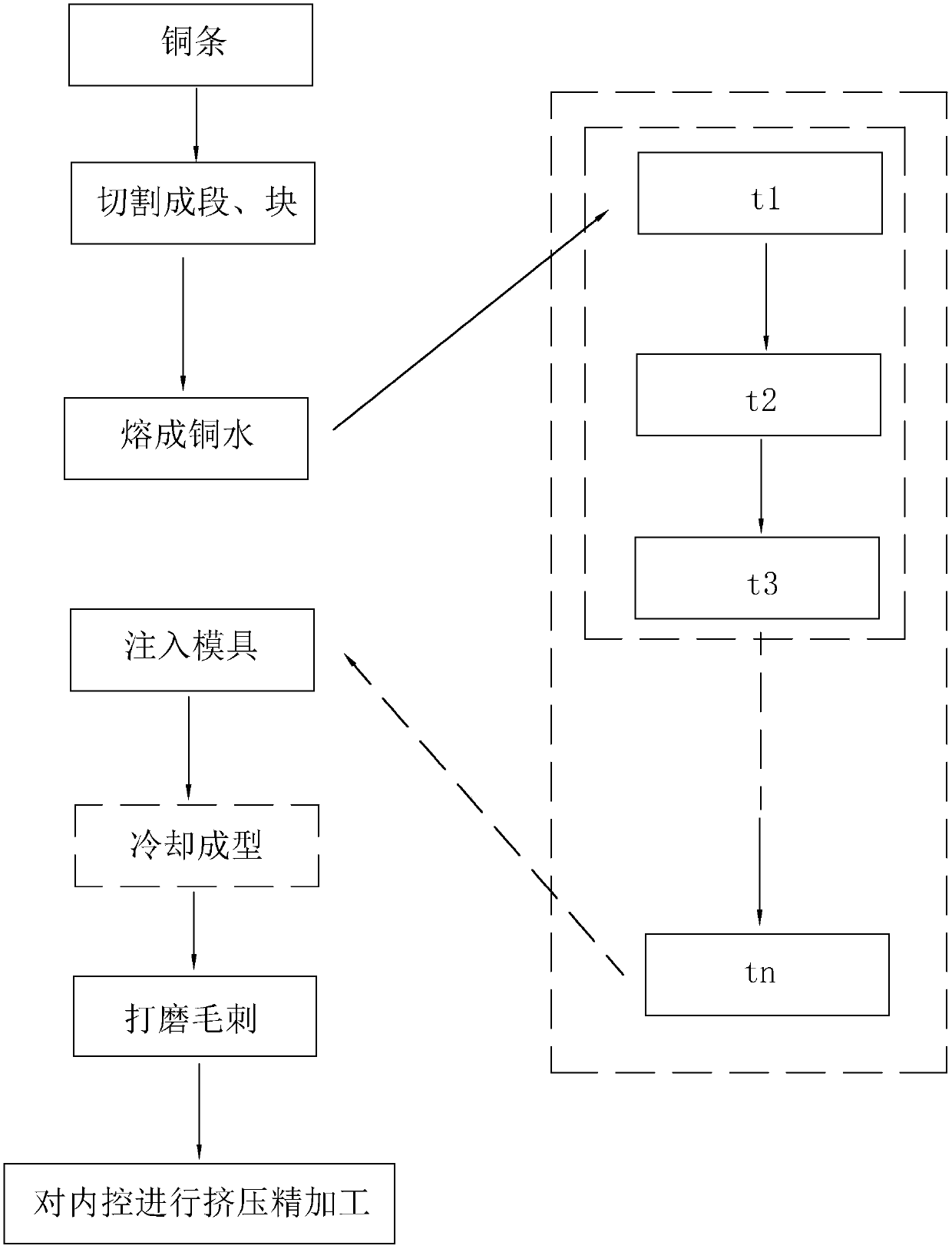
[0043] S1. Copper raw materials are cut to obtain segmented or massive copper, which is put into a furnace and heated to above 700°C to melt into liquid copper water. Inject copper water into the holding furnace for heat preservation treatment. The heat preservation process:

[0044] t1: 750°C constant temperature heat preservation, the heat preservation time is 9 to 11 minutes, and the pressure of the casting is raised to 2 to 3 times the atmospheric pressure during the heat preservation process;

[0045] t2: 700° constant temperature and heat preservation, the heat preservation time is 14 to 16 minutes, and the pressure reaches 4 times the atmospheric pressure 10 minutes before this stage;

[0046] t3: keep the temperature at 750°C for 10 to 15 minutes, and reach 5 to 7 times the atmospheric pressure before the end of this stage.

[0047] Wherein, in step t3, keep the temperat...

Embodiment 2

[0063] The processing technology for producing aluminum butterfly valves includes the following steps:

[0064] S1. Aluminum ingots are cut to obtain segmented or massive aluminum, which is put into a furnace and heated to 750°C to 800°C to melt into liquid aluminum water. Inject aluminum water into the holding furnace for heat preservation treatment. The heat preservation process:

[0065] t1: 750°C constant temperature heat preservation, the heat preservation time is 9 to 11 minutes, and the pressure of the casting is raised to 2 to 3 times the atmospheric pressure during the heat preservation process;

[0066] t2: 700° constant temperature and heat preservation, the heat preservation time is 14 to 16 minutes, and the pressure reaches 4 times the atmospheric pressure 10 minutes before this stage;

[0067] t3: keep the temperature at 750°C for 10 to 15 minutes, and reach 5 to 7 times the atmospheric pressure before the end of this stage.

[0068] Wherein, in step t3, keep the...


PUM


Abstract

The invention discloses a valve machining technology, and relates to the technical field of valve machining and manufacturing. The valve machining technology specifically comprises the steps that S1,metal raw materials are cut, and segment-shaped or blocky metal is obtained and thrown into a melting furnace to be heated and melted into liquid metal water; S2, a die is thrown into a medium-frequency heating furnace to be heated to the temperature ranging from 200 DEG C to 300 DEG C; S3, the die is taken out of the medium-frequency heating furnace and is installed on a die casting machine; S4,the metal water is pressed and injected into the die through the die casting machine; S5, the die is taken out and cooled, and a preliminarily-formed blank is obtained; S6, the blank is subjected to deburring treatment; S7, an inner hole of the blank is subjected to extrusion finish machining, and a finished valve body is obtained; S8, the valve body is subjected to metal flaw detection and otherdetection; and S9, the valve body and related components are assembled, and packaging and delivery are conducted after sampling inspection. According to the machining technology, the metal water is not prone to film formation in advance before the die is filled with the metal water.

Description

technical field [0001] The invention relates to the technical field of processing and manufacturing of valves, in particular to a processing technology of valves. Background technique [0002] The Chinese invention patent whose publication number is CN103612072B discloses a process for processing the valve body of a stop valve, such as figure 1 As shown, the copper rod is cut into sections, and then put into a furnace to melt into copper water at a temperature of 700°C, and the copper water is poured into the mold, and after natural cooling, the mold is opened to form a blank. [0003] Then deburring the hair fittings, finishing the holes in the valve by extrusion, and finally get the valve. [0004] However, in the process of injecting copper water into the mold, since the temperature of the mold is basically the same as that of the working environment, there is a large temperature difference between 10°C to 40°C and the temperature of the copper water from 650°C to 700°C....

Claims


Application Information

Patent Timeline
IPC IPC(8): B23P15/00
CPCB23P15/001
Inventor 姚军
Owner ZHENJIANG YIBAO ELECTRICAL TECH CO LTD
Why Eureka
Try Eureka