Large-scale grounding grid high-frequency characteristic test method using grounding grid current reflow

A technology of high-frequency characteristics and test methods, applied in the high-voltage field, can solve the problems of large inductance, difficult current lead, high-frequency current obstruction, etc., to achieve accurate measurement results, easy to output high-frequency current, and reduce measurement workload Effect

Active Publication Date: 2018-03-27
STATE GRID SHAANXI ELECTRIC POWER RES INST +1
View PDF9 Cites 6 Cited by
  • Summary
  • Abstract
  • Description
  • Claims
  • Application Information

AI Technical Summary

Problems solved by technology

However, the diagonal length of the UHV substation grounding grid can reach hundreds of meters, and the position of the return point that meets the requirements is often one kilometer or even several kilometers away. It is difficult to arrange the current leads for a long distance, and the on-site workload is huge.
And there is a large inductance in the lead wire that is too long, which has a large obstacle to the high-frequency current
At the same time, due to the limitation of site conditions, the laid return electrode can only be arranged simply, and the grounding resistance is very large.
The inductance of the long lead wire and the grounding resistance of the return electrode lead to a large impedance of the entire loop. Since the high-frequency power supply generally has a small power, the current cannot be output.

Method used


Image

  • Large-scale grounding grid high-frequency characteristic test method using grounding grid current reflow
  • Large-scale grounding grid high-frequency characteristic test method using grounding grid current reflow
  • Large-scale grounding grid high-frequency characteristic test method using grounding grid current reflow

Examples


Embodiment Construction

[0032] In order to make the purpose, technical solutions and advantages of the embodiments of the present invention clearer, the technical solutions in the embodiments of the present invention will be clearly and completely described below in conjunction with the drawings in the embodiments of the present invention. Obviously, the described embodiments It is a part of embodiments of the present invention, but not all embodiments. Based on the embodiments of the present invention, all other embodiments obtained by persons of ordinary skill in the art without making creative efforts belong to the protection scope of the present invention.

[0033] In the description of the present invention, it should be noted that the terms "center", "upper", "lower", "left", "right", "vertical", "horizontal", "inner", "outer" etc. The indicated orientation or positional relationship is based on the orientation or positional relationship shown in the drawings, and is only for the convenience of...


PUM


Abstract

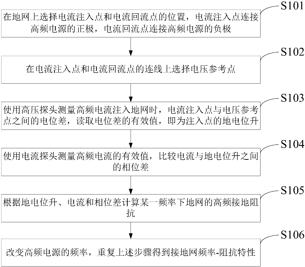
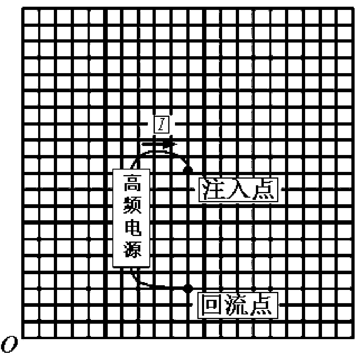
The invention discloses a large-scale grounding grid high-frequency characteristic test method using grounding grid current reflow. The method includes the following steps that: the position of a current injection point and a current reflow point are selected from a grounding grid, the current injection point is connected with the positive pole of a high-frequency power source, and the current reflow point is connected with the positive pole of the high-frequency power source; a voltage reference point is selected from a section between the current injection point and the current reflow point;a high-voltage probe is used to measure potential difference between the current injection point and the voltage reference point when high-frequency current is injected into the grounding grid, the effective value of the potential difference is read, namely, ground potential rise of the injection point can be obtained; a current probe is adopted to measure the effective value of the high-frequency current, phase difference between the current and the ground potential rise is obtained through comparison; the high-frequency grounding impedance of the grounding grid under a certain frequency iscalculated according to the ground potential rise, the current and the phase difference; and the frequency of the high-frequency power source is changed, the above steps are repeated, so that the frequency-impedance feature of the grounding grid can be obtained.

Description

technical field [0001] The invention relates to the field of high-voltage technology, in particular to a method for testing the high-frequency characteristics of a large-scale grounding grid using the backflow of the grounding grid. Background technique [0002] In order to meet the needs of work and safety in the power system, it is often necessary to connect some parts of the power system and its electrical equipment to the earth, which is grounding. In order to ensure reliable grounding of the substation, it is necessary to bury the grounding grid underground in the substation. The size of the grounding grid can be equivalent to the area of ​​the substation. [0003] At present, the main index for assessing the performance of the grounding grid is the power frequency grounding resistance of the grounding grid. The size of the grounding resistance evaluates the performance of the grounding grid. [0004] Short-circuit faults to ground and lightning strikes are common acc...

Claims


Application Information

Patent Timeline
Patent Type & Authority Applications(China)
IPC IPC(8): G01R31/00
CPCG01R31/00
Inventor 李志忠王森张波蒙泳昌何金良余占清
Owner STATE GRID SHAANXI ELECTRIC POWER RES INST
Why Eureka
Try Eureka