
Charging circuit and capacitanc power switching circuit thereof

A technology of power conversion circuit and charging power supply, which is applied in the field of capacitive power conversion circuit and charging control, charging circuit that can double the current and constant voltage charging, and can solve problems such as difficult selection of inductors and switches, and difficult design optimization.

Active Publication Date: 2018-03-27
RICHTEK TECH
View PDF5 Cites 5 Cited by
  • Summary
  • Abstract
  • Description
  • Claims
  • Application Information

AI Technical Summary

Problems solved by technology

figure 2 The disadvantage of the prior art shown in is that, especially under the requirement of a relatively large constant charging current ICHG, in the switching charging circuit 60, it is difficult to select an inductor and a switch (not shown) with proper specifications to balance the charging current. , current ripple amplitude, switch on-resistance, energy conversion efficiency and other parameters optimization, resulting in design optimization is not easy to achieve

Method used


Image

  • Charging circuit and capacitanc power switching circuit thereof
  • Charging circuit and capacitanc power switching circuit thereof
  • Charging circuit and capacitanc power switching circuit thereof

Examples


Embodiment Construction

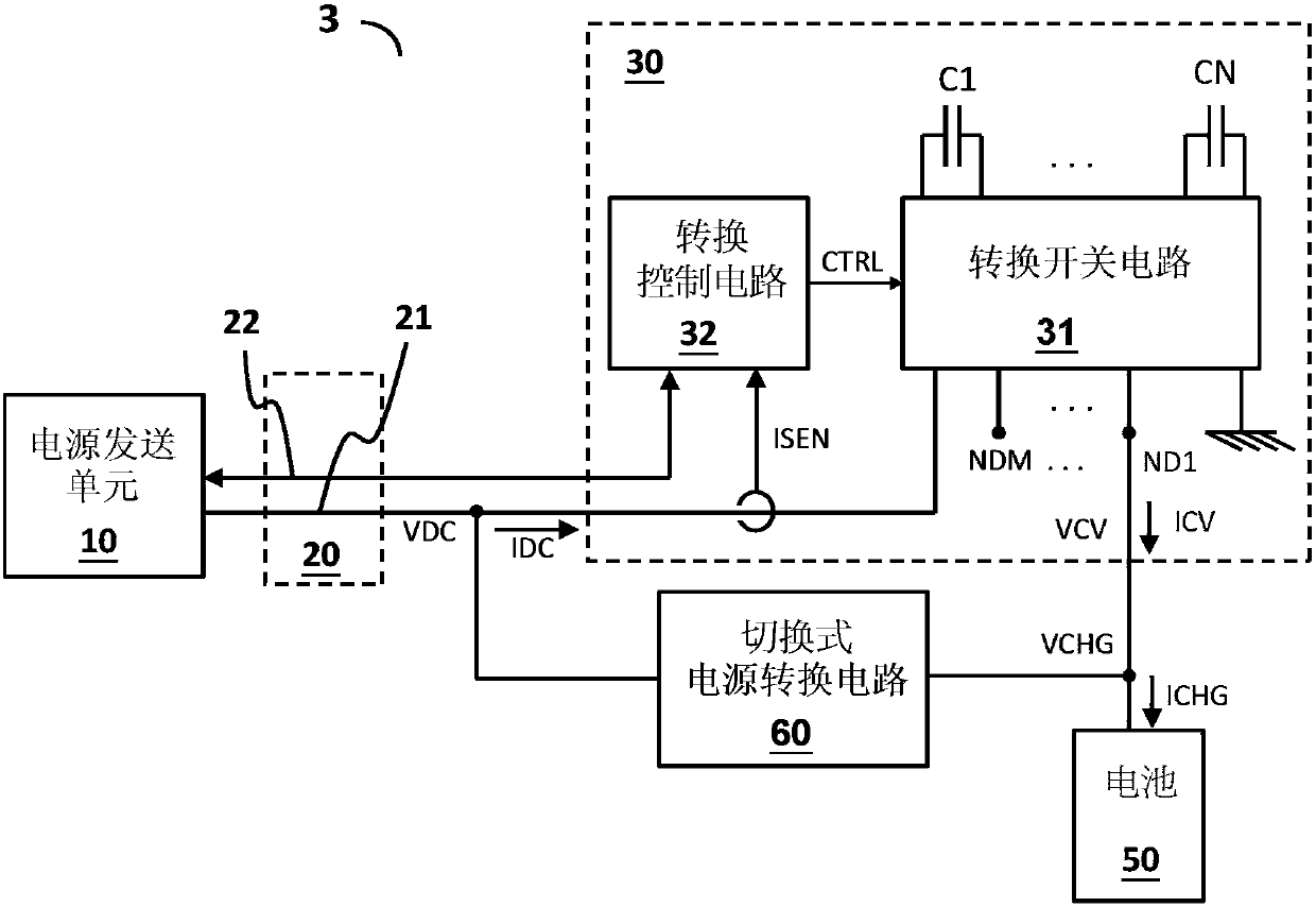
[0020] see image 3 , shown in the figure is a schematic diagram of an embodiment (charging circuit 3) of the charging circuit of the present invention, the charging circuit 3 is used to convert a DC power supply into a charging power supply to charge a battery 50, wherein the DC power supply includes a The DC voltage VDC and a DC current IDC, the charging power supply includes a charging voltage VCHG and a charging current ICHG; the charging circuit 3 includes: a power transmission unit 10 and a capacitive power conversion circuit 30 . The power transmission unit 10 converts an input power (not shown) into the DC power, and the power transmission unit 10 can be, for example, a power adapter, which converts the input power of the AC form into the aforementioned DC output power, or can be always The DC-to-DC conversion circuit converts the input power from, for example, a mobile power bank (power bank) into the aforementioned DC output power. The capacitive power conversion ci...


PUM


Abstract

The utility model provides a be used for providing a charging current's charging circuit to a battery, contains a power transmitting element and a capacitanc power switching circuit. This power transmitting element is a direct current output current and adjusts this direct current output current accurate in a predetermined output current position with an input power switching over, this capacitancpower switching circuit includes a change over switch circuit that has a plurality of change over switch, its with one or a plurality of changeover condenser be coupled, an and conversion control circuit, for in a plurality of conversion period, correspond these a plurality of change over switch of operation, make this one or a plurality of changeover condenser periodically correspond and be coupled in one or a plurality of partial pressure node, this direct current output voltage, and between this ground point a pair of node wherein, and via this one or a plurality of partial pressure node in a node produce this charging current, wherein this charging current's position standard roughly is the flow increasing multiple of the accurate acquiescence in this predetermined output current position. The utility model discloses still provide to be used for charging circuit's capacitanc power switching circuit.

Description

technical field [0001] The invention relates to a charging circuit, in particular to a charging circuit capable of multiplying current and charging with constant voltage. The invention also relates to a capacitive power conversion circuit and a charging control method used in the charging circuit. Background technique [0002] figure 1 A prior art charging circuit (charging circuit 1) is disclosed, which includes a power adapter (adaptor) 11 with direct charging capability, which can provide DC current IDC directly through a cable 20 (such as a USB cable) and a load The switch 40 (load switch) charges a battery 50 with a constant current (CC, constant current), wherein the DC current IDC is substantially equal to the charging current ICHG. However figure 1 With the prior art shown in , when using a standard cable such as a USB cable, the current limit of the cable is generally relatively low, such as about 5A or less, and the charging time is thus longer. If you want to ...

Claims


Application Information

Patent Timeline
IPC IPC(8): H02J7/00H02M3/156
CPCH02J7/007H02M3/156
Inventor 黄宗伟黄顺煜
Owner RICHTEK TECH
Learn More