Predicted camshaft phasing

A camshaft, transfer function technology, applied in electrical control, machine/engine, output power, etc., can solve problems such as optimization without providing fill detection function calculation, and achieve the effect of high overall accuracy

Active Publication Date: 2020-09-11
VOLKSWAGEN AG
View PDF8 Cites 0 Cited by
  • Summary
  • Abstract
  • Description
  • Claims
  • Application Information

AI Technical Summary

Problems solved by technology

This method allows an accurate determination of the phasing of an adjustable camshaft, but does not provide optimization for the calculation of the fill detection function

Method used


Image

  • Predicted camshaft phasing
  • Predicted camshaft phasing
  • Predicted camshaft phasing

Examples


Embodiment Construction

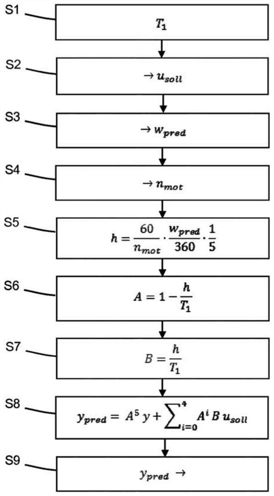
[0025] In the method according to the invention for predicting a future camshaft position, a control circuit comprising a camshaft position controller and a control device is approximated by a transfer function, and the future camshaft position is ascertained based on the transfer function.

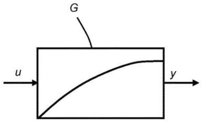
[0026] An example of a transfer function in figure 1 shown in . The transfer function G approximates the system performance. The transfer function G has an input variable u and an output variable y. The transfer function G models the system performance, ie how the output variable y of the system responds to changes in the input variable u of the system.

[0027] In the exemplary embodiments described below, the transfer function describes in particular a control circuit consisting of a camshaft position controller and a control device of a motor vehicle.

[0028] As mentioned at the outset, the fresh air ratio in the combustion chamber is largely influenced by the opening and closing t...


PUM


Abstract

The present invention relates to a method for predicting the future camshaft position (y pred ), wherein the regulating circuit comprising at least one regulating device (9) or a part of the regulating circuit is approximated by a transfer function (G), and the future camshaft position (y pred ).

Description

technical field [0001] The present invention relates to a method, computer program and engine controller for predicting the phase of a camshaft. Background technique [0002] In an unadjusted camshaft drive, the camshaft is driven at half the speed of the crankshaft through a solid connection such as a toothed belt, chain or gears. However, the solid coupling of the camshaft to the crankshaft leads to inefficient cylinder filling, ie a non-optimal fresh air ratio in the combustion chamber. Therefore, in gasoline engines, the proportion of fresh air in the combustion chamber is detected by the fill detection function in the engine controller. The proportion of fresh air in the combustion chamber is largely influenced by the switching times of the gas exchange valves. In order to achieve the most effective cylinder filling possible in all rev ranges, the intake and exhaust control times are varied depending on the rev and throttle state by means of camshaft adjustment. Adju...

Claims


Application Information

Patent Timeline
IPC IPC(8): F01L1/34F01L1/352F01L1/356F02D41/00
CPCF02D41/009F02D41/0002F01L2800/00F01L2800/14F02D2041/001F01L1/344F01L2820/02F02D2041/1412F02D2041/1422F02D2041/1432F02D13/0219Y02T10/12Y02T10/40F02D41/1402
Inventor M.汤姆福德S.施韦格
Owner VOLKSWAGEN AG
Why Eureka
Try Eureka