Clutch device for a hybrid drive system

A clutch device and clutch technology, applied in fluid-driven clutches, mechanical-driven clutches, non-mechanical-driven clutches, etc., can solve problems such as limited application range, poor micro-vibration isolation, and large restoring force

Active Publication Date: 2018-03-27
SCHAEFFLER TECH AG & CO KG
View PDF9 Cites 2 Cited by
  • Summary
  • Abstract
  • Description
  • Claims
  • Application Information

AI Technical Summary

Problems solved by technology

However, this has a limited range of application and, when the torque to be transmitted is high, the isolation especially of small

Method used


Image

  • Clutch device for a hybrid drive system
  • Clutch device for a hybrid drive system
  • Clutch device for a hybrid drive system

Examples


Embodiment Construction

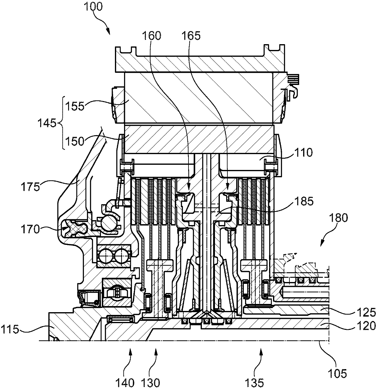
[0024] figure 1 An exemplary clutch arrangement 100 is shown. Arranged around the axis of rotation 105 is a first input 110 , a second input 115 , a first output 120 and a second output 125 .

[0025] A first clutch 130 is located between the first input 110 and the first output 120, a second clutch 135 is located between the first input 110 and the second output 125, and an optional third clutch 140 is located at the first input 110 and the second input terminal 115. The first and second clutches 130 and 135 are radially or preferably axially offset from one another and form an axial double clutch. The third clutch 140 is preferably axially offset from at least one of the first clutch 130 and the second clutch 135 .

[0026] The first input 110 is provided to be connected to an electric motor 145 which typically includes a rotor 150 and a stator 155 . The electric machine 145 is preferably of the inner rotor type, wherein the rotor 150 is located radially inward of the st...


PUM


Abstract

The invention relates to a clutch device comprising and a first and a second input side and a first and a second output side, the input sides and the output sides can be rotated together about a rotational axis. Said clutch device also comprises a first clutch between the first input side and the first output side and a second clutch is arranged between the first input side and the second output side. A third clutch is arranged between the first input side and the second input side and is a centrifugal pendulum absorber.

Description

technical field [0001] The invention relates to a clutch device. The invention relates in particular to a clutch arrangement for a hybrid drive train. Background technique [0002] The motor vehicle has a first drive motor designed as an electric machine and a second drive motor designed as an internal combustion engine. The drive of the motor vehicle can be a hybrid drive, ie realized with any combination of the first and / or second drive motor. For this purpose, a clutch arrangement is arranged between the drive engine and the transmission of the motor vehicle. [0003] DE 10 2009 059 944 A1 relates to a clutch arrangement for a hybrid-drive motor vehicle. [0004] Torsional vibrations can be transmitted to the drive train via the internal combustion engine. In order to prevent torsional vibrations from being transmitted via the drive train as much as possible, spring dampers are usually used. However, this has a limited range of application and, when the torque to be t...

Claims


Application Information

Patent Timeline
IPC IPC(8): F16D21/06B60K1/00
CPCF16D2021/0661F16D2021/0692Y10S903/914F16D25/10F16D25/082F16D25/0638F16D21/06F16D2021/0607B60K6/387B60Y2200/92F16D13/46F16D13/52F16D2021/0669F16D2300/22F16F15/145
Inventor 埃尔马·洛伦兹
Owner SCHAEFFLER TECH AG & CO KG
Why Eureka
Try Eureka