Drive device

A driving device, multi-driving technology, applied in the direction of output power conversion device, lamp testing, electrical components, etc., can solve problems such as expensive

Active Publication Date: 2018-03-27
DENSO CORP
View PDF15 Cites 2 Cited by
  • Summary
  • Abstract
  • Description
  • Claims
  • Application Information

AI Technical Summary

Problems solved by technology

However, SiC is more expensive than silicon, and semiconductor device

Method used


Image

  • Drive device
  • Drive device
  • Drive device

Examples


no. 1 approach

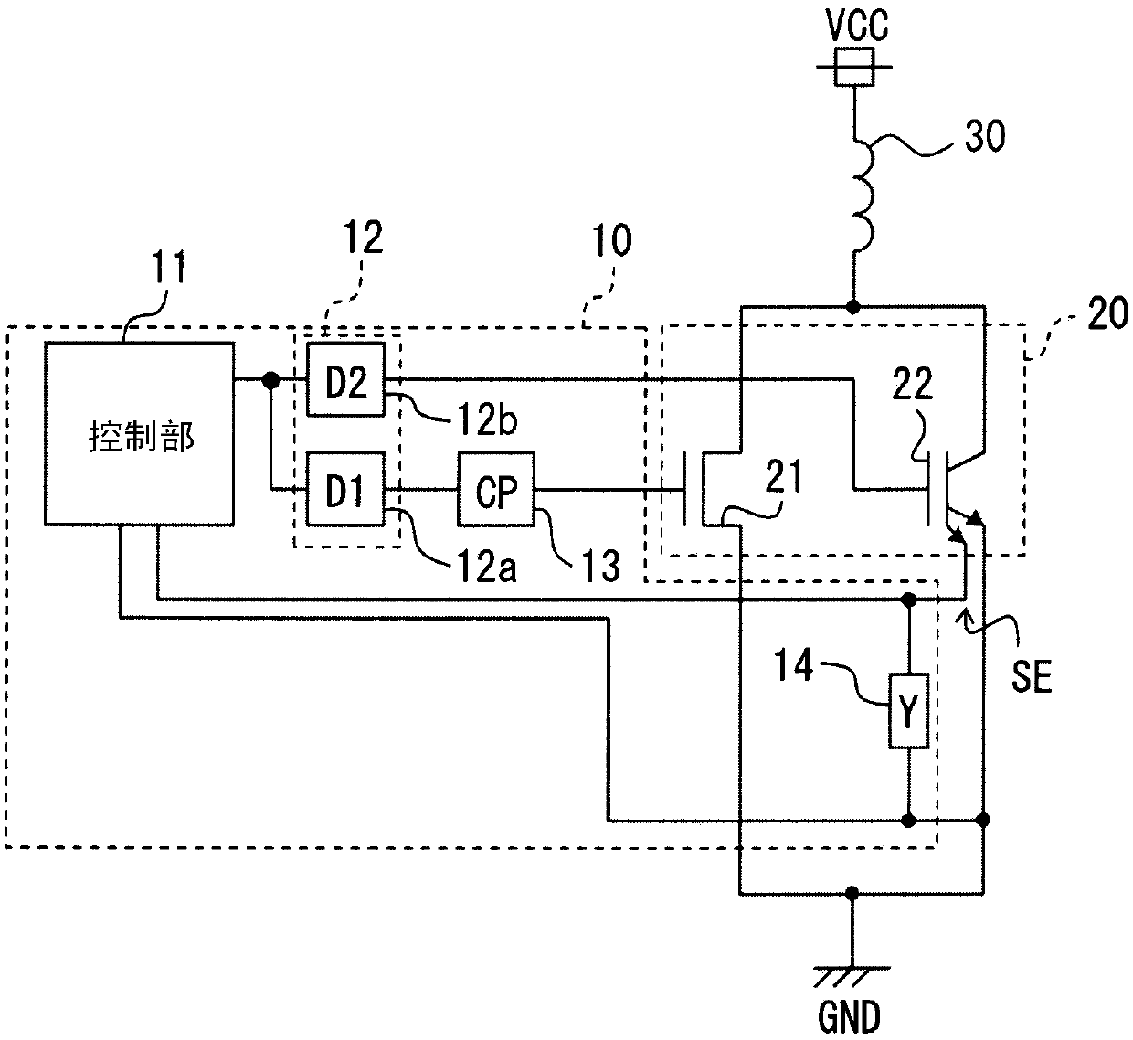
[0021] First, refer to figure 1 The schematic configuration of the drive device according to this embodiment will be described.

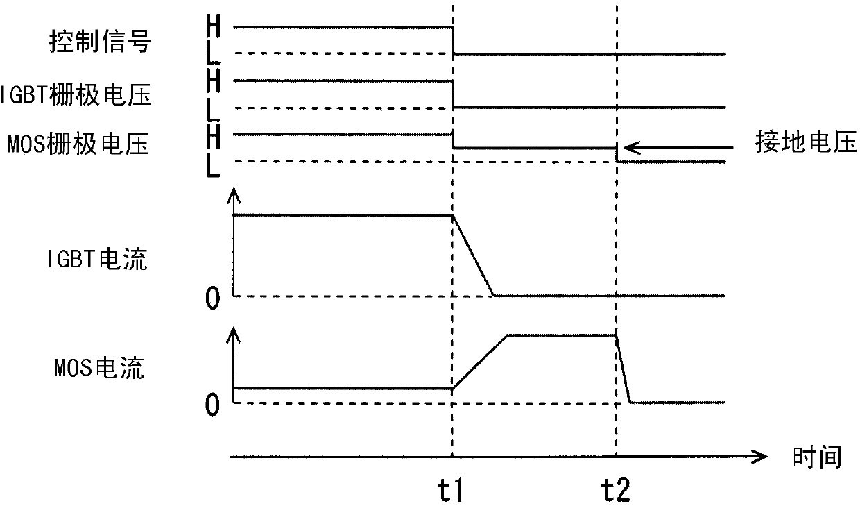
[0022] The drive device in this embodiment is used, for example, in a semiconductor device that obtains an output current by connecting two switching elements, a MOSFET and an IGBT, in parallel. An IGBT has a characteristic of generating a tail current when it is turned off. This tail current is the cause of increased switching loss at the time of shutdown. On the other hand, in a semiconductor device in which a MOSFET and an IGBT are connected in parallel, the power consumption due to the tail current is suppressed by making the timing of turning off the MOSFET later than that of the IGBT.

[0023] like figure 1 As shown, the driving device 10 in this embodiment is a device that supplies a gate voltage to the gates of the MOSFET 21 and the IGBT 22 connected in parallel between the main power supply VCC and the ground GND, and drives them. The M...

no. 2 approach

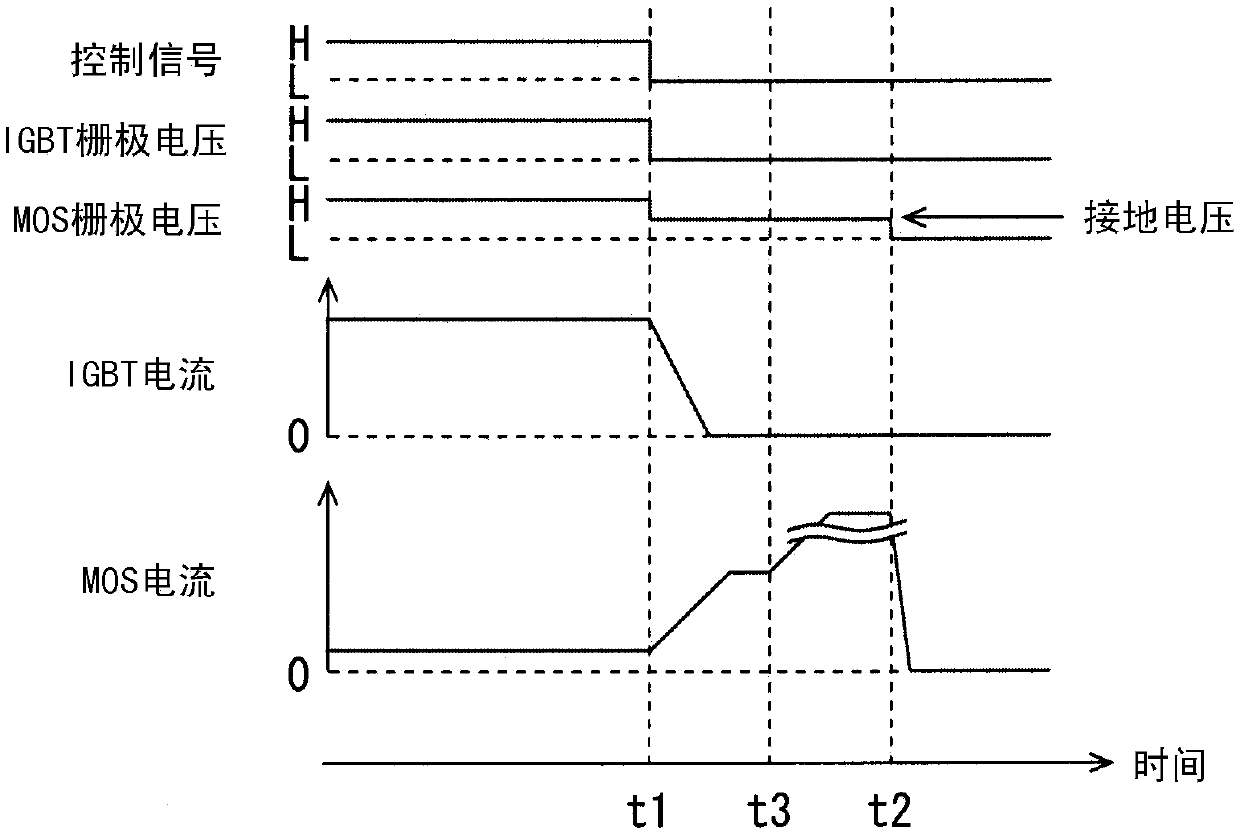
[0046] like Figure 4 As shown, the drive device 10 in this embodiment includes a gate voltage detection unit 15 ( Figure 4 GD). The configuration other than the gate voltage detection unit 15 is the same as that of the first embodiment, and thus detailed description thereof will be omitted.

[0047] The gate voltage detection unit 15 is connected to the gate of the IGBT 22 corresponding to the second switching element. The gate voltage detection unit 15 detects the gate voltage applied to the IGBT 22 by the second driver 12 b, and feeds back the value to the control unit 11 .

[0048] In the first embodiment, an example was described in which the control unit 11 sets the gate voltage of the MOSFET 21 as the clamp voltage on the condition that the control signal transitions from H to L as a trigger condition. However, the control unit 11 in this embodiment is based on The gate voltage of IGBT 22 detected by gate voltage detection unit 15 determines the gate voltage in the ...


PUM


Abstract

This drive device drives a plurality of switching elements (20), which include a first switching element (21) and a second switching element (22) and each have a gate electrode, in parallel. The drivedevice is provided with a driver (12) that supplies a voltage to the gate electrode, and a control unit (11) that outputs a control signal to the driver and controls the on/off state of the switchingelements. The control unit has, as control modes, a multi-drive mode in which both the first switching element and the second switching element are driven, and a single-drive mode in which only the first switching element is driven. In the single-drive mode, the control unit sets the gate voltage to be applied to the gate electrode of the first switching element to a clamp voltage that is smallerthan the gate voltage in the multi-drive mode.

Description

[0001] Cross-reference of related applications [0002] This application is based on Japanese application No. 2015-107449 filed on May 27, 2015, and the description thereof is incorporated herein. technical field [0003] The present disclosure relates to a driving device that drives a plurality of switching elements in parallel. Background technique [0004] The combined switch circuit described in Patent Document 1 is a circuit that drives MOSFETs and IGBTs in parallel. When the IGBT is turned off, a tail current is generated, which causes an increase in switching loss. Therefore, in the composite switching circuit described in Patent Document 1, driving is adopted in which the MOSFET is continuously driven for a certain period of time after the IGBT is turned off, and the MOSFET is finally turned off. [0005] In recent years, semiconductors mainly composed of SiC (silicon carbide) have been put into practical use. Compared with silicon, SiC has a higher dielectric bre...

Claims


Application Information

Patent Timeline
IPC IPC(8): H03K17/56H02M1/08
CPCH03K17/08128H03K17/164H03K17/127H03K2217/0036G01R19/0092H03K5/08H02M1/08H03K17/56G01R31/2608H03K17/567G01R31/44
Inventor 柿本规行
Owner DENSO CORP
Why Eureka
Try Eureka