U-shaped pipe bending mechanism

A bending mechanism and U-shaped tube technology, applied in the field of U-shaped tube bending mechanism, can solve the problems of difficult processing of U-shaped tubes, flattened tube walls, wrinkling, etc.

Pending Publication Date: 2018-03-30
ZHONGSHAN JINGDA TEKE MACHINERY CO LTD
View PDF7 Cites 5 Cited by
  • Summary
  • Abstract
  • Description
  • Claims
  • Application Information

AI Technical Summary

Problems solved by technology

However, the copper tube with thinner tube wall is softer, and it is easy to be flattened or wrinkled on the tube wall during bending processing, which affects the quality of the finished product.
Moreover, due to the limitation of the volume of the machine head, the existing bending equipment is difficult to process the U-shaped tube with a small center distance.

Method used


Image

  • U-shaped pipe bending mechanism
  • U-shaped pipe bending mechanism
  • U-shaped pipe bending mechanism

Examples


Embodiment Construction

[0026] The present invention will be described in further detail below in conjunction with the accompanying drawings.

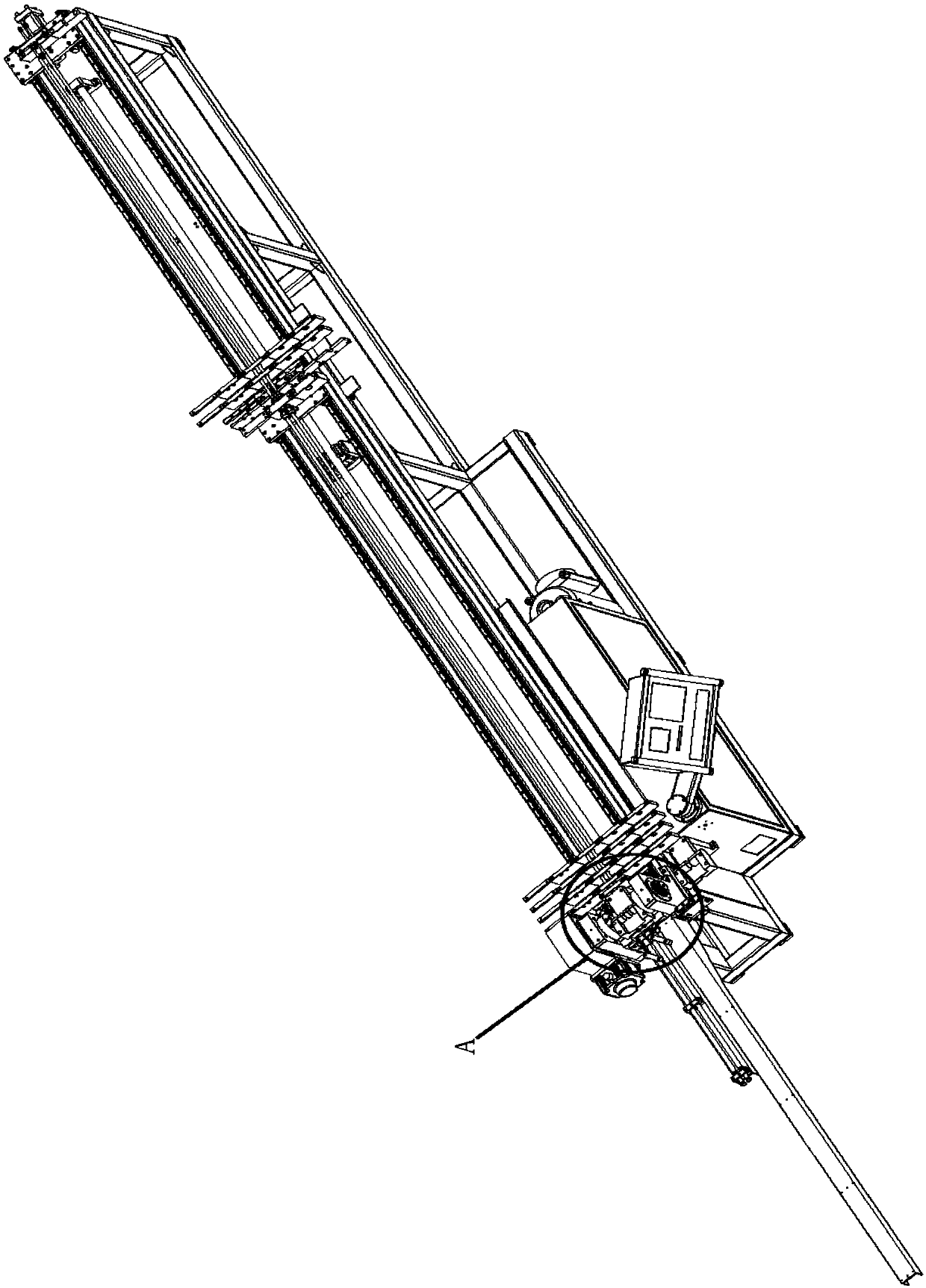
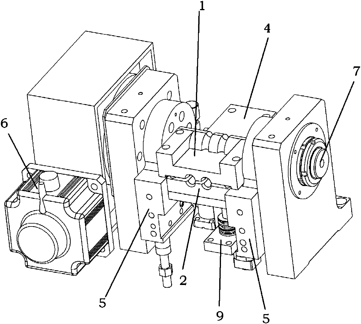
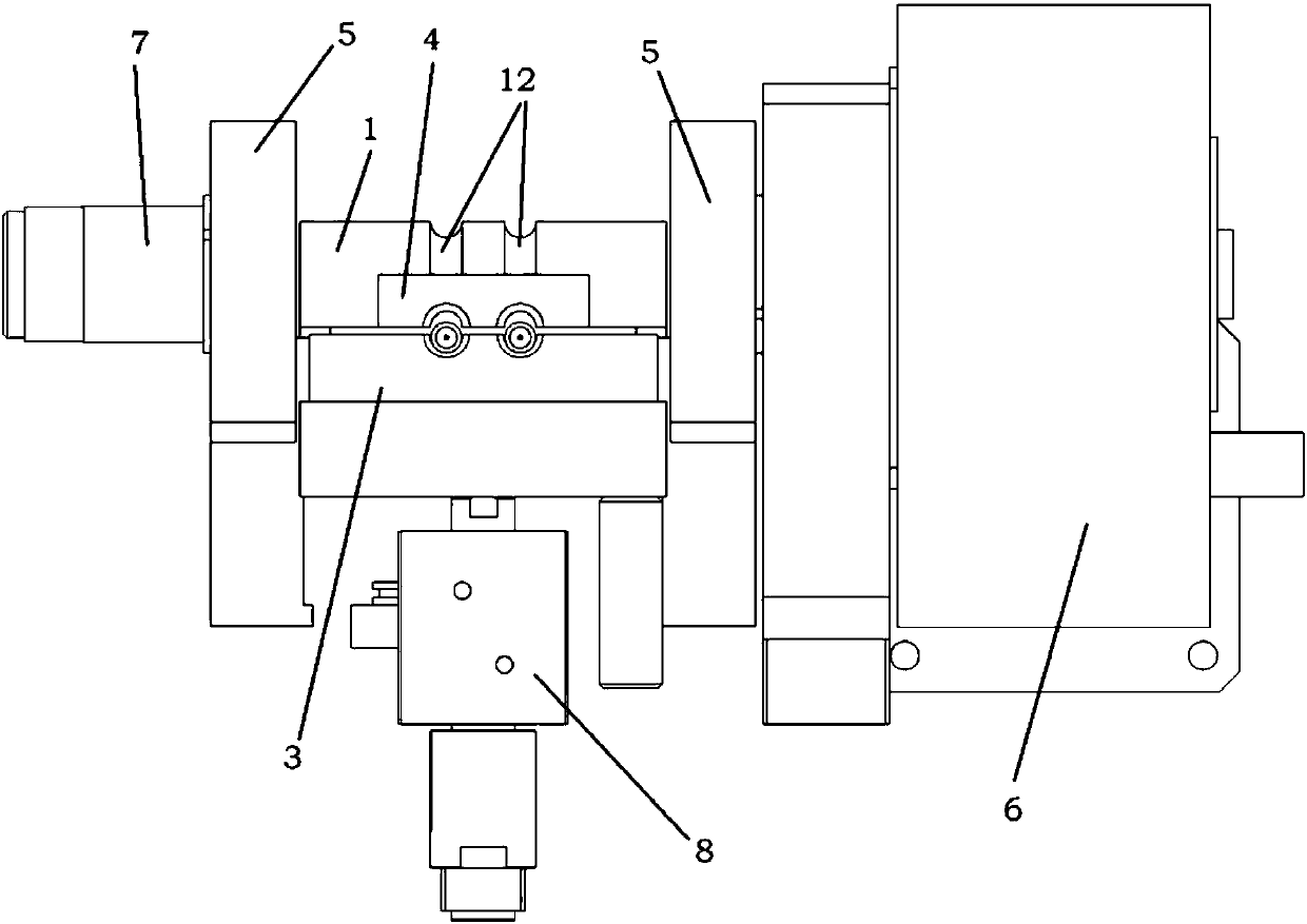
[0027] Figure 1 to Figure 8 A U-shaped tube bending mechanism according to an embodiment of the present invention is schematically shown. As shown in the figure, the device includes a bending die 1 , a clamping die 2 and a cam 3 .

[0028] The pipe passes between the bending die 1 and the clamping die 2 .

[0029] The former 3 is located on the same side of the pipe fitting as the clamping die 2 .

[0030] The inner side of the bending die 1 is an arc-shaped bending die surface 11 .

[0031] When bending, the clamping die 2 approaches the bending die 1 to clamp the pipe, and then the clamping die 2 and the bending die 1 clamp the pipe as a whole and turn it around with the central axis of the bending die surface 11 as the axis. Bending along the bending die surface 11 under the action of the bending die, so as to be processed into a predetermined shape. ...


PUM

PropertyMeasurementUnit
angleaaaaaaaaaa
angleaaaaaaaaaa

Abstract

The invention discloses a U-shaped pipe bending mechanism which comprises a bending die, a clamping die and a back die. A pipe penetrates the part between the bending die and the clamping die. The back die is arranged on the side, the same with the clamping die, of the pipe. The inner side of the bending die is an arc bending die face. A crease-resisting back die is further arranged on the side, the same with the bending die, of the pipe. The crease-resisting back die corresponds to the back die. The pipe penetrates the part between the crease-resisting back die and the back die, and the crease-resisting back die abuts against the face of the bending die. The face, making contact with the face of the bending die, of the crease-resisting back die is an arc face, the arc face is matched withthe bending die, and the top end of the side, making contact with the pipe, of the arc face stretches in the side, close to the clamping die, of the bending die. By means of the U-shaped pipe bendingmechanism adopting the above technical scheme, the pipe can be flattened, in addition, the pipe cannot be wrinkled due to stress during bending, and the U-shaped pipe bending mechanism is particularly suitable for machining pipes with thin walls or soft pipes.

Description

technical field [0001] The invention relates to a pipe fitting forming device, in particular to a U-shaped pipe bending mechanism. Background technique [0002] U-shaped tubes, generally made of copper tubes, are the main accessories of heat exchange tubes. In actual use, it is generally connected with a short U-shaped joint to form a U-shaped tube radiator, which is widely used in the field of heat exchange. [0003] Because copper is relatively expensive, in order to save costs, the industry tends to use copper tubes with thinner tube walls to process heat exchange tube fittings such as U-shaped tubes. However, the copper tube with thinner tube wall is softer, and it is easy to be flattened or wrinkled on the tube wall during bending processing, which affects the quality of the finished product. Moreover, due to the limitation of the volume of the machine head, the existing bending equipment is difficult to process the U-shaped tube with a small center distance. Conten...

Claims


Application Information

Patent Timeline
Patent Type & Authority Applications(China)
IPC IPC(8): B21D7/08
CPCB21D7/085
Inventor 肖世军黄广治肖世文肖世祥夏涛
Owner ZHONGSHAN JINGDA TEKE MACHINERY CO LTD
Why Eureka
Try Eureka