Blanking machine heat radiating device

A technology of heat sink and punching machine, used in metal processing equipment, forming tools, manufacturing tools, etc., can solve the deformation and aging of punching head, the failure of punching equipment, and the impact of punching head and punching base on the precision of punching equipment. To achieve the effect of saving consumption and avoiding waste

Pending Publication Date: 2018-03-30
YANCHENG FANGTIAN NON WOVEN PORDUCTS CO LTD
View PDF0 Cites 3 Cited by
  • Summary
  • Abstract
  • Description
  • Claims
  • Application Information

AI Technical Summary

Problems solved by technology

[0002] The punching machine is a commonly used punching and breaking equipment on the market. The main principle of its work is to cut or punch the raw materials passing through the punching machine through the punching head. During friction, impact and friction will generate a lot of heat; therefore, the punching head and the punching base will be in a state of high temperature for a long time. Long-term high-temperature operation will cause deformation and aging of the punching head itself, and the punching after aging The punching head and the punching base seriously affect the accuracy of the punching equipment, and the punching head and the punching base that cannot be completely matched will even cause the punching equipment to break down

Method used


Image

  • Blanking machine heat radiating device

Examples


Embodiment 1

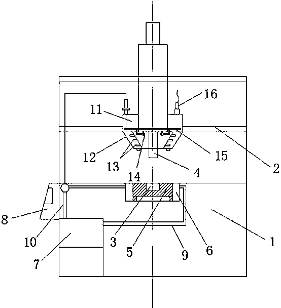
[0013] Embodiment 1: as figure 1 A punching machine heat dissipation device is shown, the heat dissipation device includes a punching head heat dissipation assembly, a base heat dissipation assembly and a cooling water storage tank 7, and the punching head heat dissipation assembly is installed on the fixed top of the punching head 4 On the bracket 2, the base heat dissipation assembly is composed of a heat dissipation connector 5 and a cooling water jacket 6. The heat dissipation connector 5 is covered on the punching groove 3 of the base 1, and the cooling water jacket 6 is coated on the outside of the heat dissipation connector 5. The punching head heat dissipation assembly includes a fixed jacket 11, a water transfer ring pipe 15 and a water mist nozzle 14. The water mist nozzle 14 is connected to the water transfer ring pipe 15 Above, the water mist nozzles 14 are symmetrically installed on both sides of the punching head 4 , and the cooling water storage tank 7 is connec...

Embodiment 2

[0014] Embodiment 2: as figure 1 As shown, an annular interlayer 12 is provided below the fixed jacket 11, and the interlayer 12 is a tapered structure with a small diameter in the lower part and a large diameter in the upper part; Fog, so that water mist gathers on the punching head 4, to avoid the spread of water mist.

Embodiment 3

[0015] Embodiment 3: as figure 1 As shown, the inner side of the interlayer 12 is evenly distributed with a plurality of air injection ports 13, the bottom of the interlayer 12 is provided with two external air injection ports, and the top of the fixed jacket 11 is provided with an air pressure pipeline 16, and the air pressure pipe The road 16 is connected to the air injection port 13 and the external air injection port, and the air pressure line 16 is connected to the air pump; the interlayer 12 can not only be used to gather water mist, but also can dry the surface of the punching head 4 through the jet air flow, and absorb the heat. The water mist is blown out of the jacket through the air flow to avoid the accumulation of water mist, which is more conducive to the drying of the punching head 4.


PUM


Abstract

The invention discloses a heat dissipation device of a punching machine, which comprises a heat dissipation assembly of a punching head, a heat dissipation assembly of a base and a cooling water storage tank, the heat dissipation assembly of the punching head is installed on a fixed bracket above the punching head, and the heat dissipation assembly of the base is connected by a heat dissipation The heat dissipation connector is covered on the punching groove of the base, and the cooling water jacket is wrapped on the outside of the heat dissipation connector. The heat dissipation assembly of the punching head includes a fixed jacket, a water delivery ring pipe and The water mist nozzle, the water mist nozzle is connected to the water delivery ring pipe, the water mist nozzle is installed symmetrically on both sides of the punching head, and the cooling water storage tank is connected to the cooling water jacket and the water delivery ring pipe in turn through the water delivery pipeline; the present invention The punching head of the punching machine is fully dried through the combination of water and airflow, and the cooling water on the punching base and the punching head is combined to save the amount of cooling water, avoid waste, and be convenient and environmentally friendly. It does not affect the normal operation of the equipment.

Description

technical field [0001] The invention relates to the auxiliary technical field of punching machines, in particular to a device for facilitating heat dissipation of punching machines. Background technique [0002] The punching machine is a commonly used punching and breaking equipment on the market. The main principle of its work is to cut or punch the raw materials passing through the punching machine through the punching head. During friction, impact and friction will generate a lot of heat; therefore, the punching head and the punching base will be in a state of high temperature for a long time. Long-term high-temperature operation will cause deformation and aging of the punching head itself, and the punching after aging The punching head and the punching base seriously affect the accuracy of the punching equipment, and the punching head and the punching base that cannot be completely matched will even cause the punching equipment to break down. Contents of the invention ...

Claims


Application Information

Patent Timeline
Patent Type & Authority Applications(China)
IPC IPC(8): B21D28/02B21D37/16
CPCB21D28/02B21D37/16
Inventor 吴拥军
Owner YANCHENG FANGTIAN NON WOVEN PORDUCTS CO LTD
Why Eureka
Try Eureka