Disassembly process of rotor parts

A rotor body and parts technology, which is applied in the dismantling process of steam turbine rotor parts, can solve the problems of convenience, safety and reliability, poor practicability and economy, high subjective experience and technical requirements of operators, and lack of dismantling technology for rotor parts. , to achieve the effect of improving reusability, good protection, and reliable stress

Active Publication Date: 2018-03-30
DONGFANG TURBINE CO LTD
View PDF7 Cites 2 Cited by
  • Summary
  • Abstract
  • Description
  • Claims
  • Application Information

AI Technical Summary

Problems solved by technology

However, due to the lack of effective dismantling technology for the above-mentioned rotor parts in the prior art, the removal and disassembly operation of the corresponding parts on the above-mentioned rotor parts after heating is performed by the traditional "violent" disassembly method (including forcibly knocking, beating, jacking, moving, etc.) forcible disassembly
This dismantling method will not only require high subjective experience and technical requirements of the operators; it will also increase the labor intensity of the operators and reduce the efficiency of dismantling; what is more, this dismantling method usually makes the Corresponding parts-sleeves, impellers or rotor bodies are damaged and damaged to varying degrees, and the integrity of the disassembly process cannot be ensured, which is not conducive to the repair work of each part, and the scrap rate and replacement rate are high, making Substantial increase in maintenance costs
It can be seen that the existing technology for dismantling the above-mentioned rotor parts is poor in convenience, safety, reliability, practicability and economy.

Method used


Image

  • Disassembly process of rotor parts
  • Disassembly process of rotor parts
  • Disassembly process of rotor parts

Examples


Embodiment 1

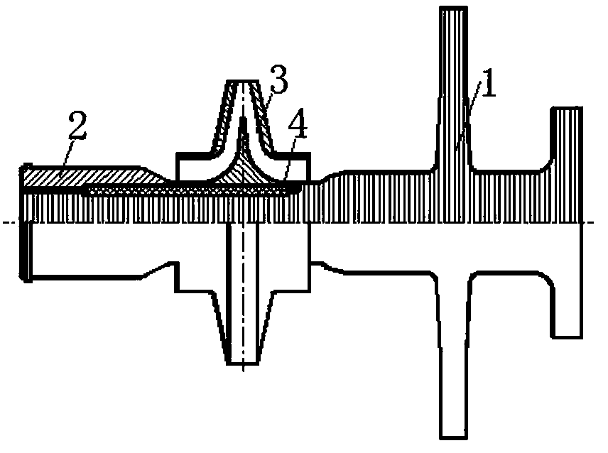
[0032] For the structure of the rotor part targeted by the present invention, see figure 1 As shown, it is mainly composed of a rotor body 1, a sleeve 2, an impeller 3 and a key 4, etc. The sleeve 2 and the impeller 3 are assembled on the rotor body 1 in an interference fit manner, and the interference is about 0.04 mm to 0.08 mm. The impeller 3 is located between the sleeve 2 and the disc on the rotor body 1 . The key 4 is fixed on the rotor body 1 with a screw tightening structure, and is located between the sleeve 2 , the impeller 3 and the rotor body 1 .

[0033] According to the structural particularity of the above-mentioned rotor parts, the present invention disassembles it in the order of first taking out the sleeve 2, then taking out the impeller 3, and then removing the key 4. Specifically, the present invention includes the following technical measures.

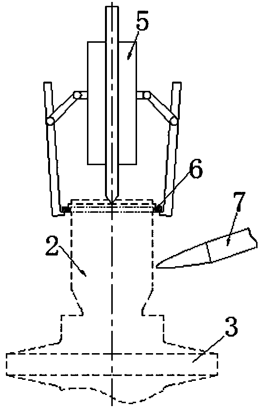
[0034] one. Regarding the disassembly and removal of the sleeve 2 on the rotor body 1 .

[0035] see figure...

Embodiment 2

[0054] The other contents of this embodiment are the same as those of Embodiment 1, the difference is that the heating of the sleeve and the impeller is carried out by electric heating plates respectively.

Embodiment 3

[0056] The other content of this embodiment is the same as that of Embodiment 1, the difference is that there is no transition ring structure on the sleeve, and the hook of the hydraulic puller is directly hooked on the convex ring on the outer circumference of the sleeve, which requires the convex ring to be in the radial direction. The raised height is high and the hook can be finally padded with pads.


PUM


Abstract

The invention discloses a disassembly process of rotor parts. The rotor parts are mainly composed of a rotor body, a sleeve and an impeller, wherein the sleeve and the impeller are assembled on the rotor body in an interference fit mode. The disassembly process comprises the following steps that 1, the sleeve on the rotor body is heated in a heating mode, and therefore the sleeve can generate thermal expansion on the rotor body, and the sleeve can keep the thermal expansion state; 2, the axial pulling is carried out on the sleeve on the rotor body at the shaft end of the rotor body by adoptinga hydraulic puller, and therefore the sleeve can be taken out from the rotor body; 3, the impeller on the rotor body is heated in a heating mode, and therefore the impeller can generate thermal expansion on the rotor body, and the impeller can keep the thermal expansion state; and 4, axial pushing is carried out on the impeller in the axial direction of the rotor body by adopting a synchronous jack, and therefore the impeller can be taken out from the rotor body. The disassembly process is capable of protecting all the parts well, and has the characteristics of being high in operability, easyand convenient, safe and efficient, good in economical efficiency, reliable, practical and the like.

Description

technical field [0001] The invention relates to a disassembly technology of integrally assembled shaft parts, in particular to a disassembly process of a steam turbine rotor part. Background technique [0002] Steam turbines usually involve the maintenance of component parts during the service process, which includes the maintenance of rotor parts. [0003] see figure 1 As shown, the rotor parts of the steam turbine are mainly composed of the rotor body 1, the sleeve 2, the impeller 3 and the key 4; among them, the sleeve 2 and the impeller 3 are assembled on the rotor body 1 in an interference fit manner, and the interference amount is about 0.04 mm~0.08mm; the key 4 is fixed on the rotor body 1 with a screw tightening structure, and is located between the sleeve 2 , the impeller 3 and the rotor body 1 . [0004] The maintenance of the rotor parts with the above structure usually involves the corresponding repair or replacement of the specific parts on the rotor parts, na...

Claims


Application Information

Patent Timeline
Patent Type & Authority Applications(China)
IPC IPC(8): B23P11/02B25B27/02
CPCB23P11/025B25B27/026
Inventor 曾强刘家顺李松林许庆国唐仕东崔志国刘艳平胥光启杨季坤
Owner DONGFANG TURBINE CO LTD
Why Eureka
Try Eureka