Eureka AIR delivers breakthrough ideas for toughest innovation challenges, trusted by R&D personnel around the world.

Wood plate polishing machine

A polishing machine, wood board technology, applied in grinding/polishing equipment, grinding/polishing safety device, grinding frame, etc., can solve the problem of easy deviation of the correct feed direction, time-consuming and labor-intensive, affecting the normal processing, etc. problems, to ensure the appearance quality, flexible operation, simple structure effect

Pending Publication Date: 2018-03-30
湖北金成光电科技股份有限公司
View PDF9 Cites 10 Cited by
  • Summary
  • Abstract
  • Description
  • Claims
  • Application Information

AI Technical Summary

Problems solved by technology

[0002] In the process of wood processing, it is often necessary to polish the wood board. The existing polishing machine cannot flexibly adjust the effective polishing range according to the size of the wood board. The wood board is easy to deviate from the correct feeding direction during the polishing process, which affects the normal processing. At the same time, debris adheres to the surface of the wood board during the polishing process, requiring additional cleaning procedures, which is time-consuming and laborious

Method used


Image

  • Wood plate polishing machine
  • Wood plate polishing machine
  • Wood plate polishing machine

Examples


Embodiment

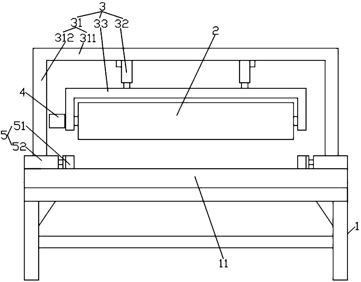
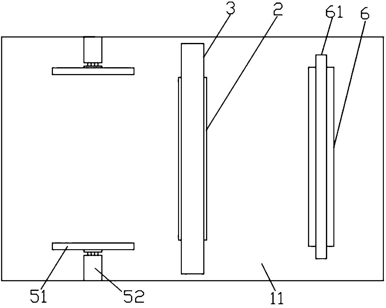
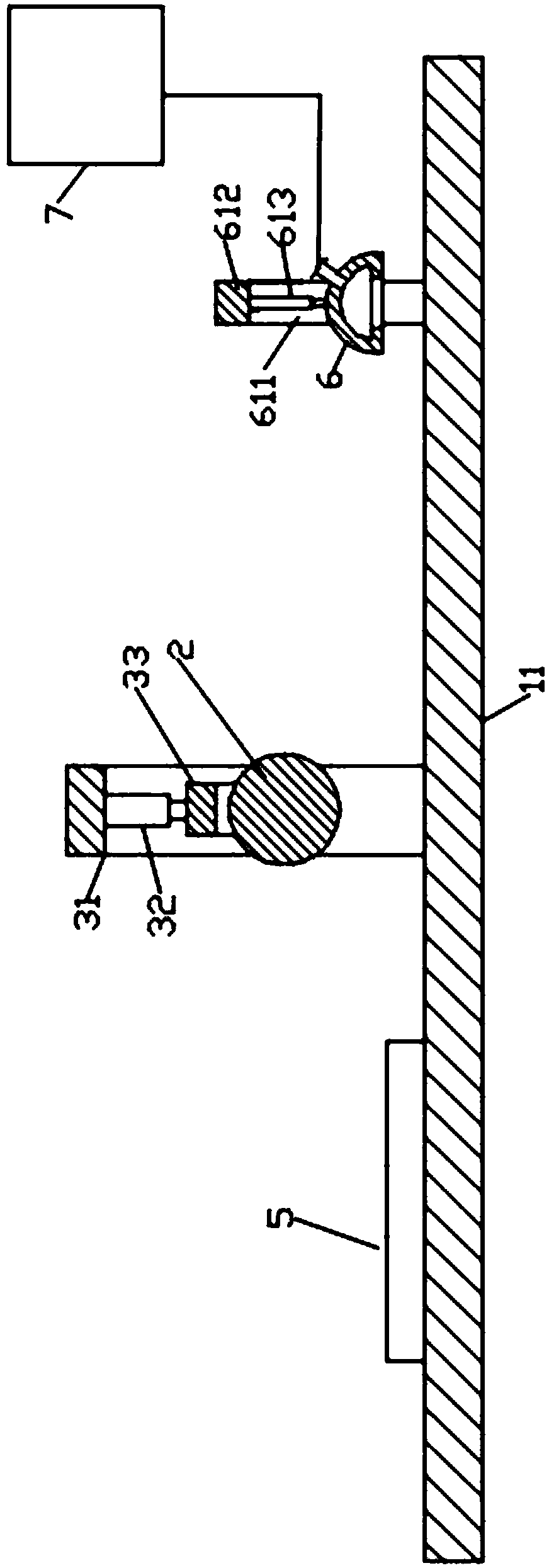
[0044] Example: such as Figures 1 to 3 As shown, the wood polishing machine of this embodiment includes a bracket 1, a sanding roller 2, a lifting mechanism 3, a driving mechanism 4, a limit guide mechanism 5 and a dust removal mechanism 6;

[0045] The upper end of the above-mentioned support 1 has a rectangular processing table 11 arranged horizontally;

[0046] The above-mentioned sanding roller 2 is horizontally arranged above the middle part of the above-mentioned processing table 11, and its two ends are respectively rotatably connected with the above-mentioned lifting mechanism 3, and the above-mentioned lifting mechanism 3 can drive the above-mentioned grinding roller 2 to move up and down to approach or move away from the above-mentioned processing table 11;

[0047] The above-mentioned driving mechanism 4 is in transmission connection with the above-mentioned sanding roller 2, and is used to drive the above-mentioned sanding roller 2 to rotate;

[0048] The above-m...


PUM


Abstract

The invention relates to a wood plate polishing machine which comprises a support, a frosting roller, a lifting mechanism, a drive mechanism, a limiting guide mechanism and a dust removal mechanism. Amachining table face is arranged at the upper end of the support. The frosting roller is transversely arranged above the middle portion of the machining table face, the two ends of the frosting roller are rotationally connected with the lifting mechanism, and the lifting mechanism can drive the frosting roller to move up and down. The drive mechanism is in transmission connection with the frosting roller. The limiting guide mechanism comprises two rectangular limiting plates, and the two limiting plates are symmetrically arranged on the two sides of the upper end of the machining table face in the length direction of the machining table face and are located on one side of the frosting roller. The sides, deviating from each other, of the two limiting plates are each provided with a pushingmechanism, and the two pushing mechanisms can push the two limiting plates correspondingly to move oppositely to be close to or away from each other. The dust removal mechanism is arranged above themachining table face and located on the other side of the frosting roller. The wood plate polishing machine has the beneficial effects that operation is flexible and convenient, it can be ensured thata wood plate is pushed in the correct direction in the machining process, and chippings on the surface of the wood plate can be cleared away in real time.

Description

technical field [0001] The invention relates to the technical field of wood processing, in particular to a wood polishing machine. Background technique [0002] In the process of wood processing, it is often necessary to polish the wood board. The existing polishing machine cannot flexibly adjust the effective polishing range according to the size of the wood board. The wood board is easy to deviate from the correct feeding direction during the polishing process, which affects the normal processing. At the same time, during the polishing process of the wood board, debris adheres to the surface of the wood board, requiring an additional cleaning process, which is time-consuming and laborious. Contents of the invention [0003] The technical problem to be solved by the present invention is to provide a wood polishing machine, which effectively overcomes the defects of the prior art. [0004] The technical solution of the present invention to solve the above-mentioned techni...

Claims


Application Information

Patent Timeline
Patent Type & Authority Applications(China)
IPC IPC(8): B24B7/28B24B7/00B24B55/06B24B55/04B24B41/00B24B41/02
CPCB24B7/005B24B7/28B24B41/00B24B41/02B24B55/04B24B55/06Y02P70/10
Inventor 陈志鹏杨红袁丹友
Owner 湖北金成光电科技股份有限公司
Why Eureka
Eureka Blog
Learn More