
Automatic power generating hub based on piezoelectric materials

A piezoelectric material, automatic power generation technology, applied in the direction of piezoelectric effect/electrostrictive or magnetostrictive motors, generators/motors, wheels, etc. Consume the driving kinetic energy of the vehicle and other problems to achieve the effect of improving the endurance, simple structure and increasing driving power consumption

Inactive Publication Date: 2018-03-30
成都皆为科技有限公司
View PDF5 Cites 2 Cited by
  • Summary
  • Abstract
  • Description
  • Claims
  • Application Information

AI Technical Summary

Problems solved by technology

Although a qualitative leap has been achieved technically, the popularization of new energy vehicles is limited in the electronic control system, battery capacity and motor system. The fundamental problem is the safety and reliability of the vehicle and the endurance of the vehicle, especially the charging of the vehicle. and battery life restrict the development of new energy vehicles
[0003] Existing mechanical power generation tires that have not been applied have complex structures and special custom tires consume vehicle driving energy and low power generation efficiency
Regardless of the comfort and safety of the vehicle, or the power generation efficiency and cost ratio, it has no practical application value.

Method used


Image

  • Automatic power generating hub based on piezoelectric materials
  • Automatic power generating hub based on piezoelectric materials
  • Automatic power generating hub based on piezoelectric materials

Examples


Embodiment 1

[0029] This embodiment is applied when the vehicle is running.

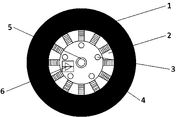
[0030] Such as figure 1 Shown, a self-generating hub based on piezoelectric materials. It is characterized in that it includes a vehicle hub structure 2 (including a flange mounting hole 3 ), a piezoelectric material assembly module 4 , an electric energy transmission slip ring 5 , and an energy recovery conversion circuit 6 .

[0031] When the vehicle is running, the wheels rotate, and the tire 1 bears the weight of the vehicle through the reaction force in contact with the ground to achieve balance.

[0032] The reaction force received by the tire 1 from the ground is transmitted to the piezoelectric material assembly module 4 through the hub 2, then to the flange of the hub, and finally to the shock absorbing bridge of the vehicle to support the vehicle body.

[0033] When the vehicle is running, the wheels transmit the force to each piezoelectric material module 4. During the rotation of the wheel, the posi...

Embodiment 2

[0037] This embodiment is applied when the vehicle is running.

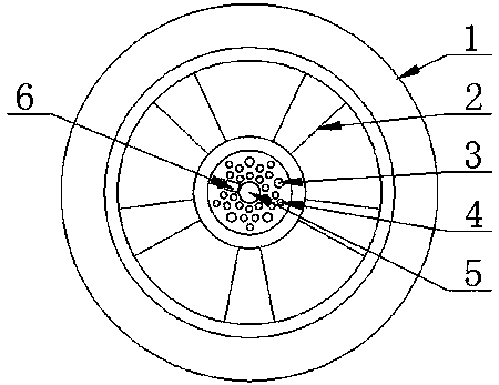
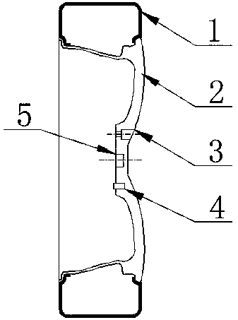
[0038] Such as figure 2 , image 3 Shown, a self-generating hub based on piezoelectric materials. It is characterized in that it includes a vehicle hub structure 2 (including a flange plate and a mounting hole 3 ), a piezoelectric material assembly module 4 , an energy recovery conversion circuit 6 , and an electric energy transmission slip ring 5 .

[0039] When the vehicle is running, the wheels rotate, and the tire 1 bears the weight of the vehicle through the reaction force in contact with the ground to achieve balance.

[0040] The reaction force received by the tire 1 from the ground is transmitted to the hub flange through the hub 2, then to the piezoelectric material assembly module 4, and finally to the vehicle shock absorber bridge to support the vehicle body.

[0041] When the vehicle is running, the wheels transmit the force to each piezoelectric material module 4. During the rotation of the wheel...


PUM


Abstract

The invention relates to the technical field of new energy vehicles, specifically to an automatic power generating hub based on piezoelectric materials. The automatic power generating hub based on thepiezoelectric materials comprises a vehicle hub (including a flange plate mounting hole), a piezoelectric material module, an energy recycling and converting circuit and an electric energy transmission slip ring. The vehicle weight is transmitted to wheels through the hub to act upon the road surface so as to achieve a balance with counter-acting force. During the running of a vehicle, the wheelsrotate, pressure is applied to the piezoelectric material module and then released from the piezoelectric material module in circulation; the piezoelectric material module generates voltage-charge and contiguously transmits the voltage-charge to the energy recycling and converting circuit to be converted into electric energy for continuous use or storing; and the electric energy for continuous use or storing is transmitted to a vehicle power device or an electric energy storage unit through the electric energy transmission slip ring. The automatic power generating hub based on the piezoelectric materials has the advantages that mechanical energy, thermal energy and so on of deformation generated by the hub under a stress in the vehicle running process are collected and converted into theelectric energy to provide power supplement to the new energy vehicle; vehicle running kinetic energy consumption is not increased; the cruising power of an electrical driving vehicle can be obviouslyenhanced and can be even enhanced by more than 20%.

Description

technical field [0001] The invention relates to the field of new energy vehicles, in particular to an automatic power generation hub based on piezoelectric materials. Background technique [0002] New energy vehicles can be divided into five categories according to power: pure electric vehicles, gas vehicles, fuel cell vehicles, hybrid vehicles, and various alternative fuel vehicles. Among them, pure electric vehicles and hybrid vehicles are developing and popularizing rapidly, especially pure electric vehicles presenting the future development trend. Although a qualitative leap has been achieved technically, the popularization of new energy vehicles is limited in the electronic control system, battery capacity and motor system. The fundamental problem is the safety and reliability of the vehicle and the endurance of the vehicle, especially the charging of the vehicle. And battery life restricts the development of new energy vehicles. [0003] Existing mechanical power gen...

Claims


Application Information

Patent Timeline
Patent Type & Authority Applications(China)
IPC IPC(8): B60B19/00B60K25/08H02N2/18
CPCH02N2/18B60B19/00B60K25/08
Inventor 李正李铭浩
Owner 成都皆为科技有限公司
Learn More