Flat-plate type extraction centrifuge

A centrifuge and flat-plate technology, which is applied in the field of centrifuges, can solve the problems of cumbersome disassembly of the upper motor, bearing seat flange, complex design structure, and residual cleaning fluid, etc., to achieve convenient daily maintenance, high production efficiency, and pollution prevention Effect

Pending Publication Date: 2018-04-03
张家港市碧鹰离心机有限公司
View PDF12 Cites 1 Cited by
  • Summary
  • Abstract
  • Description
  • Claims
  • Application Information

AI Technical Summary

Problems solved by technology

[0003] In the existing extraction centrifuges, the power device generally adopts a suspended structure, the motor is at the top, and is driven from the upper part. The design structure is complex and the center of gravity is high. In some design structures, the motor and bearing seat at the upper end need to be disassembled when adjusting the heavy phase weir plate. Flanges, etc. are very cumbersome. In addition, in the past, during maintenance, regular maintenance and inspection of extraction centrifuges, all the upper motor and bearing seat flanges must be disassembled before further operation, which is extremely inconvenient to use and easy to clean after cleaning. A lot of cleaning liquid remains in the drum, which is easy to cause material pollution after feeding

Method used


Image

  • Flat-plate type extraction centrifuge
  • Flat-plate type extraction centrifuge
  • Flat-plate type extraction centrifuge

Examples


Embodiment Construction

[0032] The present invention will be described in further detail below through specific examples.

[0033] In describing the present invention, it is to be understood that the terms "center", "level", "height", "thickness", "upper", "lower", "top", "bottom", "inner", " The orientation or positional relationship indicated by "outside", etc. is based on the orientation or positional relationship shown in the drawings, and is only for the convenience of describing the present invention and simplifying the description, rather than indicating or implying that the referred device or element must have a specific orientation, so as to Specific orientation configurations and operations, therefore, are not to be construed as limitations on the invention.

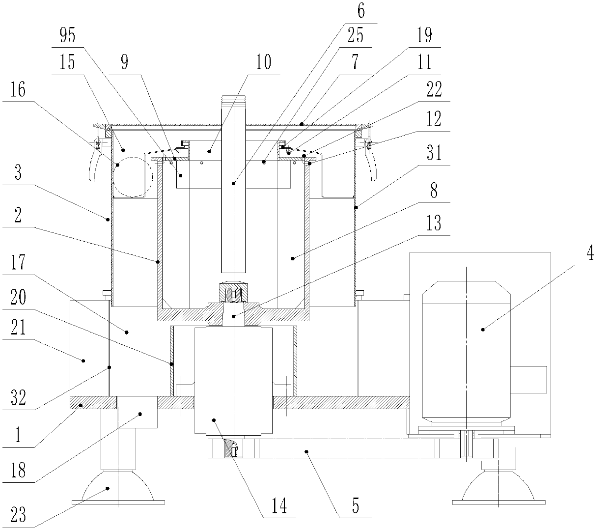
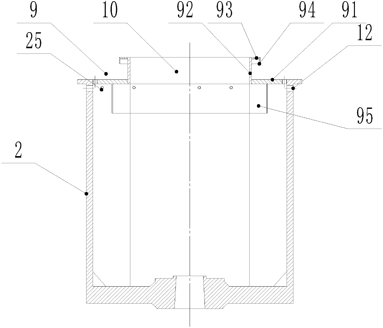
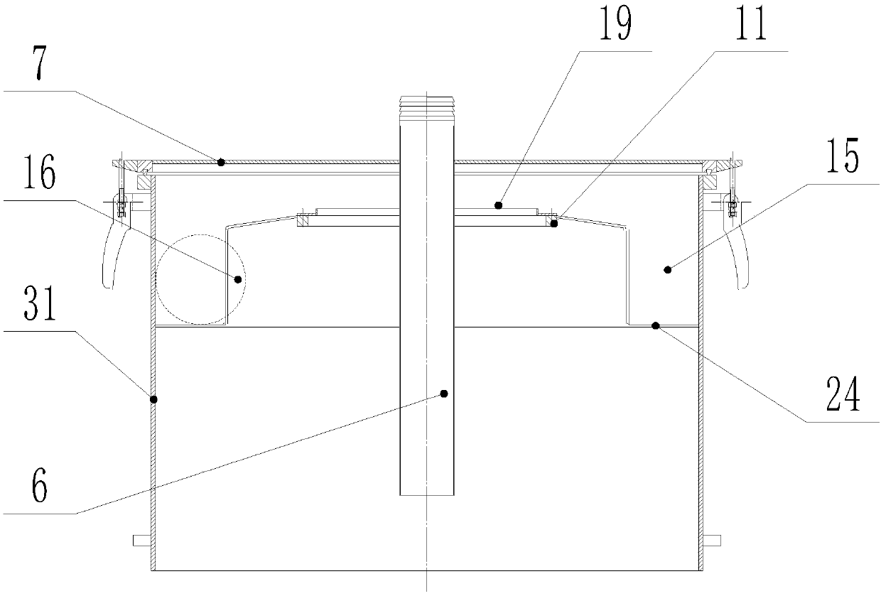
[0034] Such as Figures 1 to 5As shown, a flat type extraction centrifuge includes a flat base 1, an outer shell 3, a drum 2, a motor 4, a transmission device 5, and a feed pipe 6. The outer shell 3 is fixed on the flat base 1, and t...


PUM


Abstract

The invention discloses a flat-plate type extraction centrifuge, including a flat plate base, an outer shell, a revolving drum, a motor, a transmission device and an inlet pipe, wherein the outer shell is fixed to the flat plate base, the upper end face of the outer shell is detachably provided with a top cover, the inlet pipe is arranged on top cover and extends into the revolving drum, the upperend of the revolving drum is open, ribbed plates are uniformly distributed on the inner wall of the revolving drum, the upper end of the revolving drum is provided with a weir plate flange, the center hole of the weir plate flange is a light phase discharge hole, the side wall of the revolving drum is provided with a heavy phase discharge hole, the revolving drum is rotatably mounted on the flatplate base, the inner wall of the outer shell is provided with a light phase collection trough, the light phase collection trough extends to the lower side of the weir plate flange, a light phase collecting cavity is formed between the inner wall of the outer shell, the inner wall of the light phase collection trough and the top cover, the light phase collecting cavity is connected with a light phase discharge tube, a heavy phase collection cavity is formed between the inner wall of the outer shell, the flat plate base, the revolving drum and the outer wall of the light phase collection trough, the flat plate base is provided with a heavy phase discharge tube, and the heavy phase collection cavity communicates with the heavy phase discharge tube. The centrifuge can be quickly disassembledand assembled, and the production efficiency is high.

Description

technical field [0001] The invention relates to the field of centrifuges, in particular to an extraction centrifuge used for separating liquids with different densities. Background technique [0002] A centrifuge is a machine that uses centrifugal force to accelerate the separation of different materials that need to be separated. The extraction centrifuge is mainly suitable for the separation of liquids with different densities. It has high production efficiency and is widely used in pharmaceutical, chemical, food, environmental protection and other industries. [0003] In the existing extraction centrifuges, the power device generally adopts a suspended structure, the motor is at the top, and is driven from the upper part. The design structure is complex and the center of gravity is high. In some design structures, the motor and bearing seat at the upper end need to be disassembled when adjusting the heavy phase weir plate. Flanges, etc. are very cumbersome. In addition, i...

Claims


Application Information

Patent Timeline
Patent Type & Authority Applications(China)
IPC IPC(8): B04B1/06B04B7/02B04B7/08B04B9/02B04B15/06B04B7/00
CPCB04B1/06B04B7/00B04B7/02B04B7/08B04B9/02B04B15/06
Inventor 屠元华
Owner 张家港市碧鹰离心机有限公司
Why Eureka
Try Eureka