
Automatic stamping device

An automatic and motor-driven technology, applied in printing, stamping and other directions, can solve the problems of different sizes of drawings and inability to meet the needs of functions, and achieve the effect of improving efficiency

Inactive Publication Date: 2018-04-03
颜廷鑫
View PDF0 Cites 3 Cited by
  • Summary
  • Abstract
  • Description
  • Claims
  • Application Information

AI Technical Summary

Problems solved by technology

This method satisfies the general stamping requirements, but for the already bound architectural drawings, mechanical drawings, electrical drawings, etc., the stamping position is uncertain, the drawings are of different sizes, and the drawings are bound into books. Therefore, the existing automatic stamping technology still needs to be improved and developed

Method used


Image

  • Automatic stamping device
  • Automatic stamping device
  • Automatic stamping device

Examples


Embodiment Construction

[0022] The technical solution of this patent will be further described in detail below in conjunction with specific embodiments.

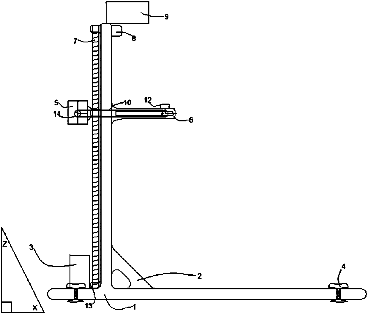
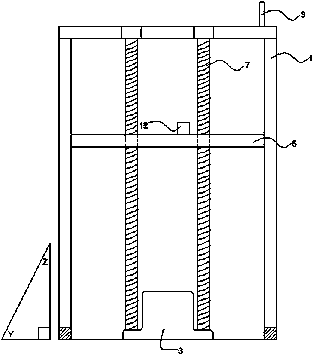
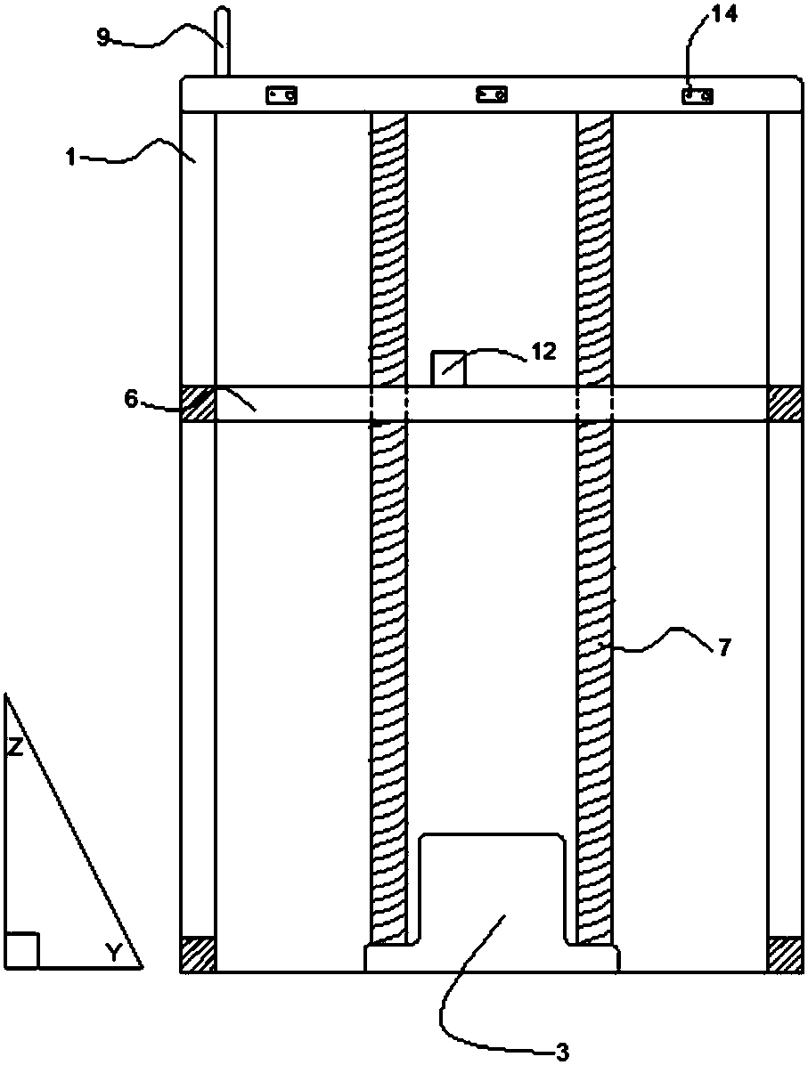
[0023] see Figure 1-7 , an automatic stamping device, comprising a main frame 1, a support plate 2 and a support 6, the main frame 1 is provided with a support 6, and the support 6 is slidingly connected with the main frame 1, and the main frame 1 is provided with T-shaped slot, the corresponding position on the support 6 contains a pulley corresponding to the T-shaped slot of the main frame 1, so that the support 6 can reduce the damping coefficient when sliding up and down to reduce friction; the main frame 1 is provided with a support plate 2 , the support plate 2 can ensure that the vertical beams of the main frame 1 are perpendicular to each other, and play a fixed support role; the upper side of the main frame 1 is fixedly equipped with a liquid crystal touch screen 9, and four balance knobs 4 are placed on the four corners of the bottom of ...


PUM


Abstract

The invention discloses an automatic stamping device, comprising a main frame, a support plate and a bracket, the main frame is provided with a bracket, the main frame is provided with a support plate, and a liquid crystal touch display is fixedly installed on the upper side of the main frame screen; a camera is also installed on the upper side of the bracket, a plurality of badge sleeves are placed on the bracket, and a control system is provided on the main frame. The automatic stamping device is set through the LCD touch screen and selects manual mode, vertical stamping mode, automatic stamping, rectangular area stamping and other modes to take pictures, calculate and analyze, drive positioning, stamping, blowing, page turning, etc. Counting, display, alarm reminder and other functions, so as to realize automatic identification, automatic positioning, automatic stamping, automatic air drying, automatic page turning, automatic stamping, and improve the efficiency of stamping.

Description

technical field [0001] The invention relates to the field of automatic stamping, in particular to an automatic stamping device. Background technique [0002] At present, the existing automatic stamping devices, including various simple stamping devices, automatic stamping devices, and automatic stamp rolling devices, are aimed at simplifying manual low-efficiency, high-repeatability actions, and they are all stamped at a fixed position in the XY axis plane. This method satisfies the general stamping requirements, but for the already bound architectural drawings, mechanical drawings, electrical drawings, etc., the stamping position is uncertain, the drawings are of different sizes, and the drawings are bound into books. Therefore, the existing automatic stamping technology still needs to be improved and developed. Contents of the invention [0003] The object of the present invention is to provide an automatic stamping device to solve the problems raised in the above-menti...

Claims


Application Information

Patent Timeline
IPC IPC(8): B41K3/62B41K3/64
CPCB41K3/64B41K3/62
Inventor 颜廷鑫
Owner 颜廷鑫
Learn More