Water pump

A technology for water pumps and pump bodies, which is applied in the direction of pump components, variable displacement pump components, and components of pumping devices for elastic fluids, etc., which can solve the problems of difficulty in reducing the radiation of the pump body itself, poor heat dissipation environment of the water pump, and protection of the water pump. Shutdown and other problems to achieve the effect of improving sound insulation and noise reduction, reducing impact, and weakening impact

Pending Publication Date: 2018-04-03
MIDEA GRP CO LTD
View PDF6 Cites 2 Cited by
  • Summary
  • Abstract
  • Description
  • Claims
  • Application Information

AI Technical Summary

Problems solved by technology

The existing technology suppresses the sound radiation of the water pump by adding the water pump casing and sound-absorbing layer, but it is easy to cause the heat dissipation environment of the water pump to be poor; for the high-speed and high-power water pumps used in large-flux water treatment equipment, this situation is particularly prominent. Easy to overheat and cause protective shutdown of the water pump
There are also existing technical solutions that use a pressure pulsation attenuation device at the outlet of the water pump, which can only reduce part of the structural vibration noise, and it is difficult to reduce the radiation of the pump body itself.

Method used


Image

  • Water pump
  • Water pump
  • Water pump

Examples


Embodiment 1

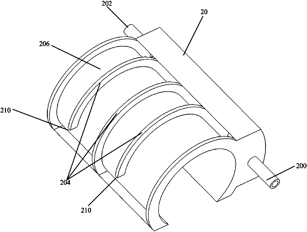
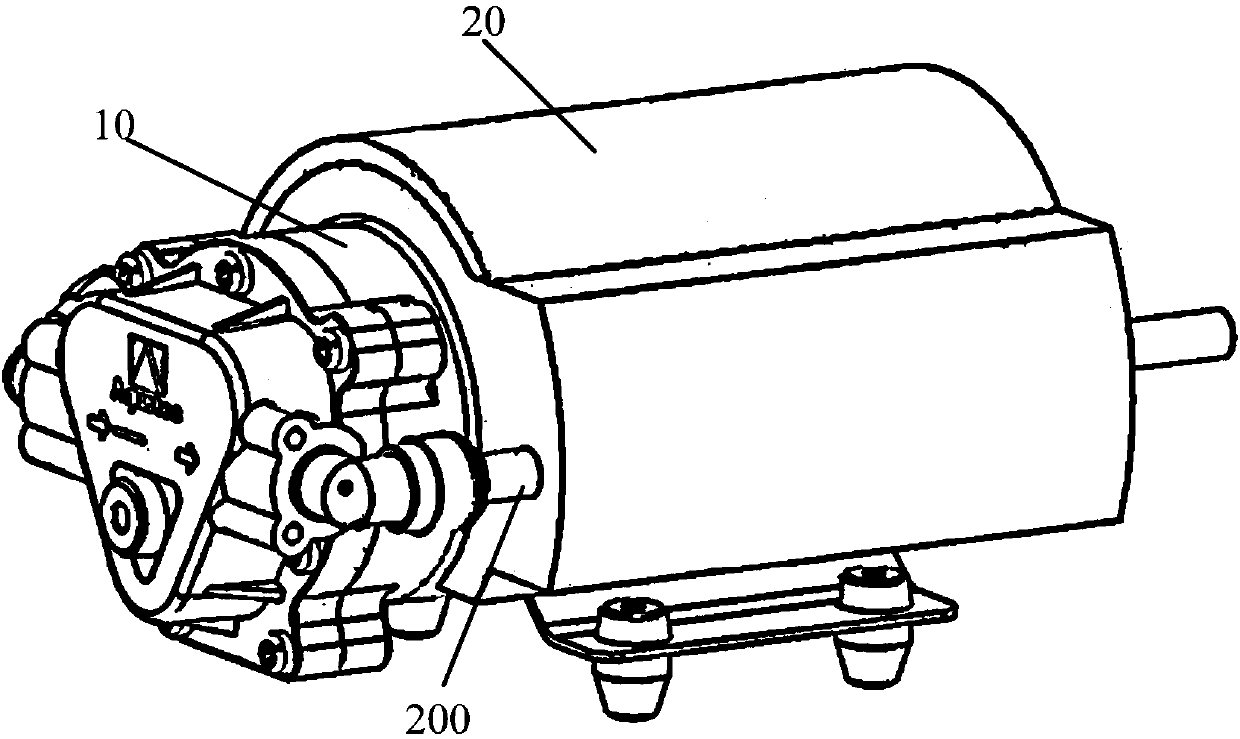
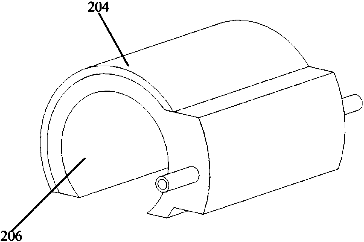
[0050] Such as Figure 1 to Figure 15 As shown, a water pump according to an embodiment of the present invention includes: a pump body 10, and a sound-insulating pulsation attenuation device 20, such as figure 2 , sleeved on the outside of the pump body 10, the sound insulation pulsation attenuation device 20 is hollow inside, including: an inner shell 206 and an outer shell 208 forming the inner cavity of the sound insulation pulsation attenuation device 20, and two end faces. Such as Figure 9 and Figure 10 ,and Figure 12 , Figure 14 , Figure 15 As shown, wherein, the inner shell 206, the outer shell 208 are concentric with the pump body 10, and are arranged along the radial direction of the pump body 10 in turn, the inner shell 206 is set between the pump body 10 and the outer shell 208, and the two end faces are along the pump body 10 is set in the direction of the centerline and is perpendicular to the centerline of the pump body 10 . The two end faces of the sou...

Embodiment 2

[0062] On the basis of Embodiment 1, this embodiment provides a manner in which the longitudinal channels 210 of the baffle 204 are distributed in the radial direction of the pump body 10 .

[0063] Such as Figure 16 As shown, the longitudinal passage 210 of the first baffle 204 of the present embodiment is between the baffle 204 and the housing 208; Being close to the water inlet makes the stress on the first baffle 204 more uniform, and the water flow can pass through the first longitudinal channel 210 faster, reducing the impact on the first baffle 204 and prolonging its service life. The longitudinal channel 210 of the second baffle 204 is between the baffle 204 and the inner shell 206 ; the longitudinal channel 210 of the third baffle 204 is between the baffle 204 and the outer shell 208 .

[0064] Through the technical solution of this embodiment, in the radial direction of the pump body 10, the projections of any two adjacent longitudinal passages 210 on the end face ...

Embodiment 3

[0067] Combining Embodiment 1 and Embodiment 2, in this embodiment, the longitudinal passages 210 on the three baffles 204 are dislocated in the circumferential direction and the radial direction at the same time, that is, in the radial direction and the circumferential direction of the pump body 10, The purpose is that the projections of any two adjacent longitudinal passages 210 on the end face of the sound insulation and pulsation attenuation device 20 do not completely coincide.

[0068] Specifically, as Figure 17 As shown, in this embodiment, only the longitudinal channel 210 on the second baffle plate 204 is arranged at the position of the middle part of the baffle plate 204, which is partial to the housing 208, so that the longitudinal channels 210 on the three baffle plates 204 can be The dislocation setting in the radial direction and the circumferential direction, and because the longitudinal channel 210 on the second baffle plate 204 is located in the center, short...


PUM


Abstract

The invention provides a water pump. The water pump comprises a pump body and a sound insulation pulse attenuation device. The sound insulation pulse attenuation device is arranged on the outer portion of the pump body in a sleeving mode, and the interior of the sound insulation pulse attenuation device is hollow. The water pump comprises water flow channels formed in the two end faces of the sound insulation pulse attenuation device correspondingly and at least one flow baffle, the flow baffles are fixedly connected with the inner wall of the sound insulation pulse attenuation device, and theflow baffles are not parallel to the center lines of the water flow channels; and gaps exist in each flow baffle and a part of the inner wall of the sound insulation pulse attenuation device, and a longitudinal channel of water flow is formed. According to the technical scheme of the water pump, on the one hand, noise brought by water pump vibration and water flow pulse is blocked, pressure pulseof the water flow is reduced through the flow baffles, and the noise is further lowered; on the other hand, vibration energy of the water pump is gradually weakened and absorbed by the water flow, the influence of water pump vibration on the structure is reduced, and the service life of the water pump is prolonged; and heat generated by working of the water pump can further be taken away by the water flow, the heat dissipating capability of the water pump is enhanced, and the working stability of the water pump is improved.

Description

technical field [0001] The invention relates to the technical field of water treatment, in particular to a water pump. Background technique [0002] With the improvement of the performance of large-flux water treatment equipment, high-speed and high-power water pumps have begun to be applied to water purifiers, but they bring huge noise and vibration, causing serious noise pollution. Due to the structural characteristics of the water pump, a large flow pulsation will be generated during operation, causing pressure pulsation. The pressure pulsation is transmitted to the water treatment equipment through the waterway, inducing structural acoustic radiation; Radiates through the enclosure into the surrounding environment. The existing technology suppresses the sound radiation of the water pump by adding the water pump casing and sound-absorbing layer, but it is easy to cause the heat dissipation environment of the water pump to be poor; for the high-speed and high-power water ...

Claims


Application Information

Patent Timeline
Patent Type & Authority Applications(China)
IPC IPC(8): F04B53/00F04B53/08F04B11/00
CPCF04B11/0091F04B53/001F04B53/08
Inventor 张肃李清李忠华
Owner MIDEA GRP CO LTD
Why Eureka
Try Eureka