Air-air heat exchanger and refrigerating device

A technology of air heat exchangers and refrigeration devices, which is applied in the direction of indirect heat exchangers, heat exchanger types, space heating and ventilation details, etc., and can solve the problems of single performance, inability to operate, and limited use of air conditioning systems

Pending Publication Date: 2018-04-03
陈祖卫
View PDF0 Cites 6 Cited by
  • Summary
  • Abstract
  • Description
  • Claims
  • Application Information

AI Technical Summary

Problems solved by technology

[0004] The present invention aims at the problem that the performance of the existing air-conditioning system is single, it cannot operate under multiple working conditions, and its use is greatly limited, and proposes an air-air heat exchanger and its refrigeration device. The air-air heat exchanger adopts M -CYCLE evaporative cooling design, with three working modes, and eight working modes after being applied to the air conditioning system, which can realize cooling, heating, and the balance of air supply and return air volume, and is suitable for various working conditions

Method used


Image

  • Air-air heat exchanger and refrigerating device
  • Air-air heat exchanger and refrigerating device
  • Air-air heat exchanger and refrigerating device

Examples


Embodiment 1

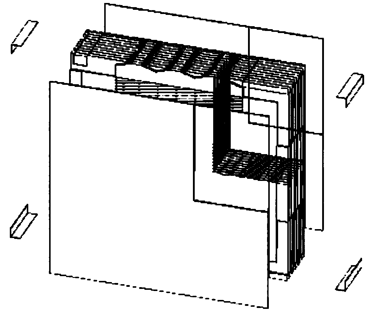
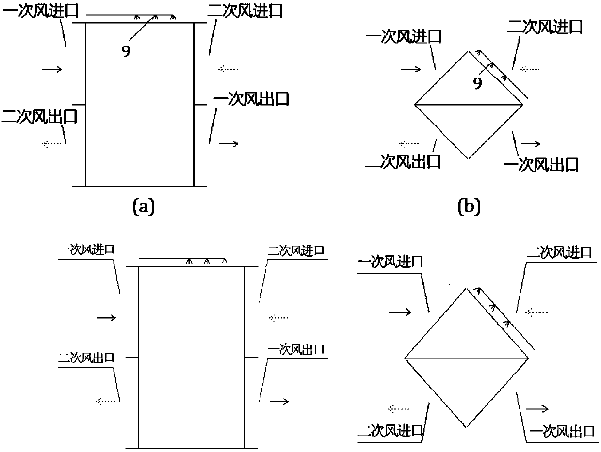
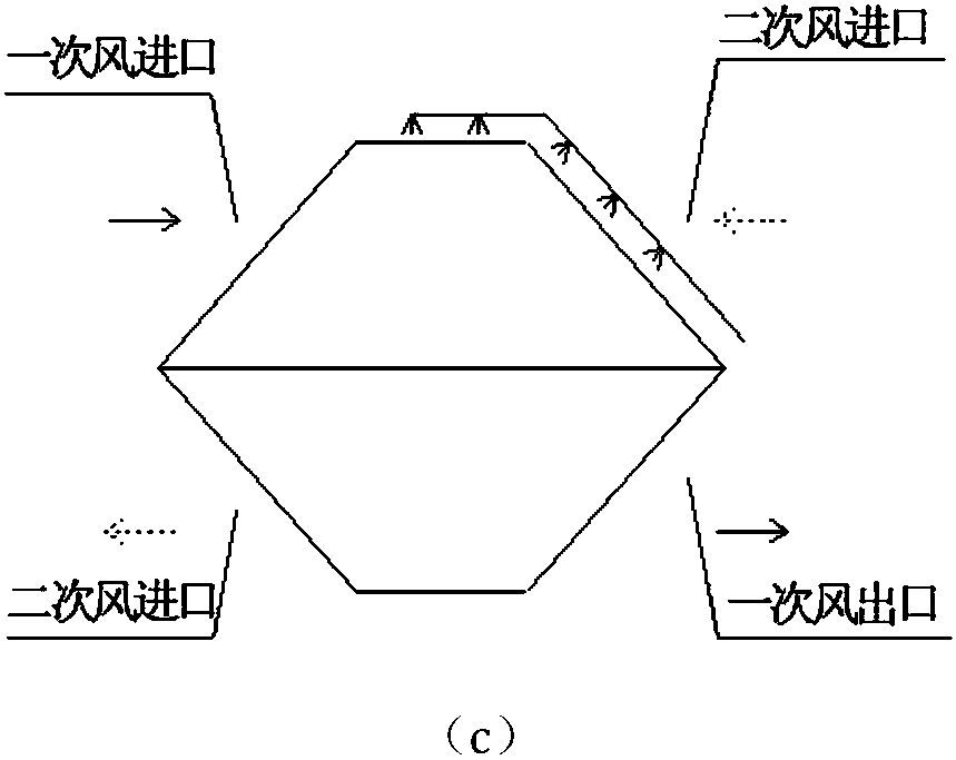
[0032] Such as figure 1 with figure 2 As shown, this embodiment relates to an air-to-air heat exchanger 8, comprising: stacked heat exchange membranes, wherein: a group of three adjacent heat exchange membranes is formed by a dry channel and a wet channel composed of heat exchange channels, the superimposed heat exchange channels constitute mutually independent primary air inlet (heat exchanger fresh air inlet 7), primary air outlet (heat exchanger fresh air outlet 20), secondary air inlet (heat exchanger return air inlet 10) and the secondary air outlet (heat exchanger return air outlet 1), the primary air inlet and the primary air outlet, the secondary air inlet and the secondary air outlet are in a diagonal relationship.

[0033] The primary air inlet, the primary air outlet, the secondary air inlet and the secondary air outlet can also be realized through heat exchange membranes and independent flow dividing and collecting mechanisms.

[0034] The heat exchange membrane...

Embodiment 2

[0057] Such as Figure 4 As shown, this embodiment further includes: a condenser 2, an evaporator 17 and a compressor 22, wherein: the condenser 2 is located between the return air fan 6 and the return air outlet 1 of the heat exchanger, and the evaporator 17 is located between the air supply fan 14 Between the fresh air outlet 20 of the heat exchanger and the air supply outlet 16 side; the compressor 22 is connected to the condenser 2 and the evaporator 17 respectively.

[0058] The compressor 22 is connected to the condenser 2 and the evaporator 17 through a four-way reversing valve 23, wherein: the main valve of the four-way reversing valve 23 is connected to the exhaust port of the compressor 22, and the three control valves are respectively connected to The air inlet of the condenser 2, the air outlet of the evaporator 17 and the air inlet of the compressor 22 are connected.

[0059] The air outlet of the condenser 2 is connected with the air inlet of the evaporator 17, ...

Embodiment 3

[0079] Such as Figure 5 As shown, this embodiment further includes: a condenser 2, an evaporator 17 and a compressor 22, wherein: the air supply fan 14 is located between the fresh air filter 5 and the fresh air inlet 7 of the heat exchanger, and the return air fan 6 is located at the return air outlet 15 and the return air inlet 10 of the heat exchanger; the condenser 2 is located between the outlet 3 and the return air outlet 1 of the heat exchanger, and the evaporator 17 is located at the end of the fresh air duct 25 near the air supply outlet 16; The condenser 2 is connected to the evaporator 17 .

[0080] This embodiment includes eight modes, namely: 100% fresh air dew point evaporative cooling mode, 100% fresh air dew point evaporative cooling + mechanical cooling mode, fresh air ratio adjustable mode, fresh air ratio adjustable + mechanical cooling mode, 100% indirect evaporative cooling mode, 100% indirect evaporative cooling + mechanical cooling mode, 100% heat reco...


PUM


Abstract

An air-air heat exchanger and its refrigeration device, the air-air heat exchanger includes laminated heat exchange membranes, each heat exchange membrane surface is provided with protrusions for forming fluid flow channels in two membranes and concave, the fluid flow channel includes a heat exchange part and a fluid distribution part, wherein: a group of heat exchange channels consisting of a dry channel and a wet channel are formed between three adjacent heat exchange membranes, and the superimposed exchange The hot aisles form independent primary air inlets and form independent primary air inlets, primary air outlets, secondary air inlets, and secondary air outlets. The primary air inlets correspond to the primary air outlets, and the secondary air inlets correspond to the secondary air outlets. ; The invention has reasonable design and various functions, and is suitable for adjusting the air volume of cooling and heating under various working conditions.

Description

technical field [0001] The invention relates to a technology in the field of air-conditioning equipment, in particular to an air-air heat exchanger and a refrigeration device thereof. Background technique [0002] The current indirect evaporative cooling has two directions, namely indirect evaporative cooling and M-CYCLE evaporative cooling. Air conditioning units combining evaporative cooling and mechanical refrigeration are mainly represented by the following two modes: one is the coupling of indirect evaporative heat exchanger and mechanical refrigeration, and the other is the coupling of M-CYCLE heat exchanger and mechanical refrigeration. [0003] The indirect evaporative heat exchanger is coupled with mechanical refrigeration. The mechanical refrigeration evaporator is placed at the air supply port of the indirect evaporative heat exchanger to provide further cooling and dehumidification; and the mechanical refrigeration condenser is placed in the working airflow of th...

Claims


Application Information

Patent Timeline
Patent Type & Authority Applications(China)
IPC IPC(8): F28D9/04F24F13/30
CPCF28D9/04F24F13/30
Inventor 陈祖卫
Owner 陈祖卫
Why Eureka
Try Eureka