Unlock instant, AI-driven research and patent intelligence for your innovation.
A kind of preparation method of optical film and product thereof
What is Al technical title?
Al technical title is built by PatSnap Al team. It summarizes the technical point description of the patent document.
A technology of optical films and products, applied in optics, optical components, nonlinear optics, etc., can solve problems such as high cost and large phase difference
Active Publication Date: 2019-11-26
安徽贝可科技有限公司
View PDF5 Cites 0 Cited by
Summary
Abstract
Description
Claims
Application Information
AI Technical Summary
This helps you quickly interpret patents by identifying the three key elements:
Problems solved by technology
Method used
Benefits of technology
Problems solved by technology
The preparation of this optical film is quite different from the existing optical film process, and the cost of mass production is relatively high
Method used
Image
Click on the blue label to locate the original text in one second.
Reading with bidirectional positioning of images and text.
Examples
Embodiment 1
[0096] Implementation example 1 relates to an optical film with free-form lenses on both surfaces. For details, please refer to figure 1 and image 3 . Proceed as follows:
[0097] 1) Set the position of the light source as (0.00,0.00), the position of the intersection of the front surface S1 and the horizontal axis (3.00,0.00), the position of the intersection of the back surface S2 and the horizontal axis (10.50,0.00), and the thickness of the substrate d=0.188mm.
[0098] 2) Set the maximum angle θ at which the light source enters the virtual lens max = 60°.
[0099] 3) In the range of [0,60], with 0.05° as the division unit, obtain a series of θ 1i , where θ 1(i+1) = θ 1i +0.05, i=1~1200.
[0100] 4) Bring i=1, 2, 3, ..., 1200 into the following function groups in turn:
[0101]
[0102] In the above group of functions, (x 1i ,y 1i ) is the angle θ emitted by the light source 1i and θ 1i-1 The intersection coordinates of the ray and the front surface S1. (x...
Embodiment 2
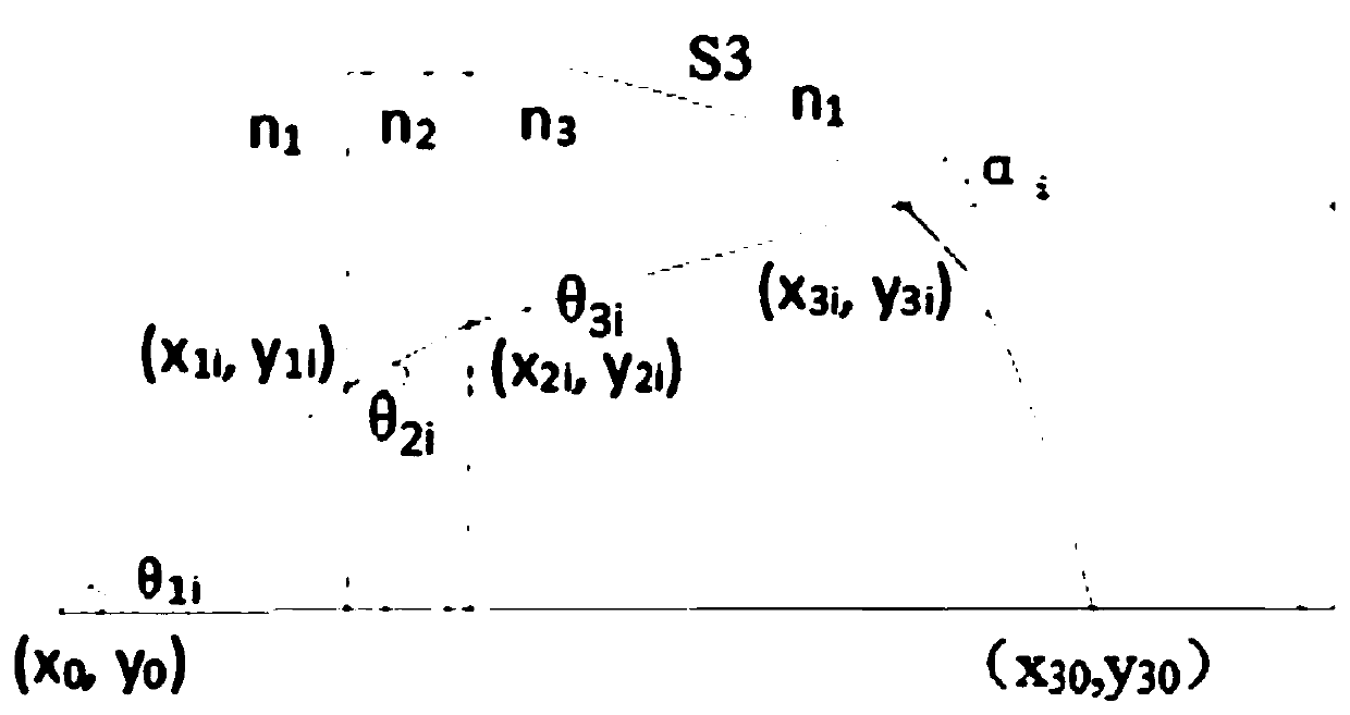
[0115] Implementation example 2 relates to an optical film with a free-form surface lens on a single surface. For details, please refer to figure 2 and Figure 5 . Proceed as follows:
[0116] 1): Determine the position of the light source (0.00, 0.00), the position of the intersection of the curved surface S3 and the horizontal axis (8.50, 0.00), and the thickness of the substrate d=0.188mm.
[0117] 2): Set the maximum angle θ at which the light source enters the virtual lens max = 60°. ;
[0118] 3): In the range of [0,60°], start at 0°, divide every 0.02°, and obtain a series of θ 1i , where θ 1(i+1) = θ 1i +3000, i=1~3000.
[0119] 4) When i=1, the angle θ=θ of the light emitted by the light source 11 = 0°, put in the following formula to solve (x 31 ,y 31 ):
[0120]
[0121] In the above formula, (x 1i ,y 1i ), (x 2i ,y 2i ) and (x 3i ,y 3i ) are respectively the angle θ emitted by the light source 1i The coordinates of the intersection of the ray w...
PUM
Property
Measurement
Unit
thickness
aaaaa
aaaaa
Abstract
The invention provides a preparation method of an optical film and a product thereof. The optical film has a surface with one or two lens shapes. The initial shape of the lens is a free-form surface obtained based on the radiation characteristics of the light source and the Snell formula, and the thickness of the lens is between 5mm-15mm. The thickness of the free-form surface lens is controlled between 10-100um after thinning treatment. The optical film with the shape of the thinned lens can be used as a master mold for direct reprinting, or a metal master mold can be obtained by electroplating for mass production. The optical film proposed by the invention can be directly used in the existing display system, and can greatly reduce the volume of the original system structure while providing a collimated light source. The design method of the optical film proposed by the invention greatly reduces the development cost and period, and the developed optical film has a good market prospect.
Description
technical field [0001] The present invention relates to the technical field of liquid crystal display and projection display, in particular to the design and preparation of an optical film capable of collimating incident light, in particular to a preparation method of the optical film and its product. Background technique [0002] After years of development, liquid crystal display has become the mainstream technology of flat panel display. Viewing angle is an important indicator of liquid crystal display, and it is generally required that the larger the viewing angle, the better. And as people pay more and more attention to personal privacy, people hope that the viewing angle of mobile phones and personal computers can be smaller, so as to ensure that the displayed content cannot be seen by people around them. In projection display, the projection light source provides illumination light. For the subsequent optical system, the higher the collimation of the incident light, t...
Claims
Application Information
Patent Timeline
Application Date:The date an application was filed.
Publication Date:The date a patent or application was officially published.
First Publication Date:The earliest publication date of a patent with the same application number.
Issue Date:Publication date of the patent grant document.
PCT Entry Date:The Entry date of PCT National Phase.
Estimated Expiry Date:The statutory expiry date of a patent right according to the Patent Law, and it is the longest term of protection that the patent right can achieve without the termination of the patent right due to other reasons(Term extension factor has been taken into account ).
Invalid Date:Actual expiry date is based on effective date or publication date of legal transaction data of invalid patent.

