
A method of operating a pedal cycle having an electro-mechanical drive arrangement

A driving device, bicycle technology, applied in the direction of electromechanical device, wheel transmission device, chain/belt transmission device, etc., can solve problems such as difficulty, pedal feedback difficulty, and no initial feedback, etc.

Active Publication Date: 2018-04-03
EBIKE SYSTEMS LTD
View PDF10 Cites 1 Cited by
  • Summary
  • Abstract
  • Description
  • Claims
  • Application Information

AI Technical Summary

Problems solved by technology

[0013] While this approach provides some benefit in the user experience, during start-up (i.e. when the bike starts from a standstill) there is no initial feedback from any of the motors because there is no current flowing when stationary
Therefore, it is difficult to provide an efficient start-up process with electric mopeds that employ the aforementioned motion or cadence sensors.
While torque sensors may help with this, such sensors have the disadvantages mentioned above
Furthermore, implementation of the system described in WO2010 / 092345 has encountered difficulties with pedal feedback; in particular, changes in the feedback provided during cycling can be particularly perceptible to cyclists not using this system

Method used


Image

  • A method of operating a pedal cycle having an electro-mechanical drive arrangement
  • A method of operating a pedal cycle having an electro-mechanical drive arrangement
  • A method of operating a pedal cycle having an electro-mechanical drive arrangement

Examples


no. 2 example

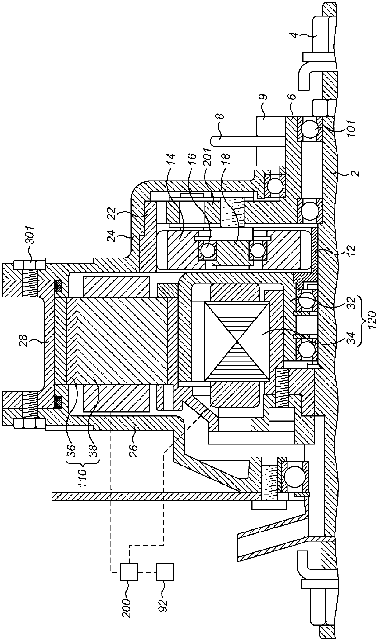
[0090] now refer to Figure 6 A second embodiment is described. with reference to Figure 1 to Figure 5 Like reference numerals denote like features compared to the described embodiments.

[0091] In the second embodiment, no output motor is provided. Alternatively, the input motor 120 provides all electrical control to the system. Figure 6 The hub 100 is shown in detail in an alternate embodiment.

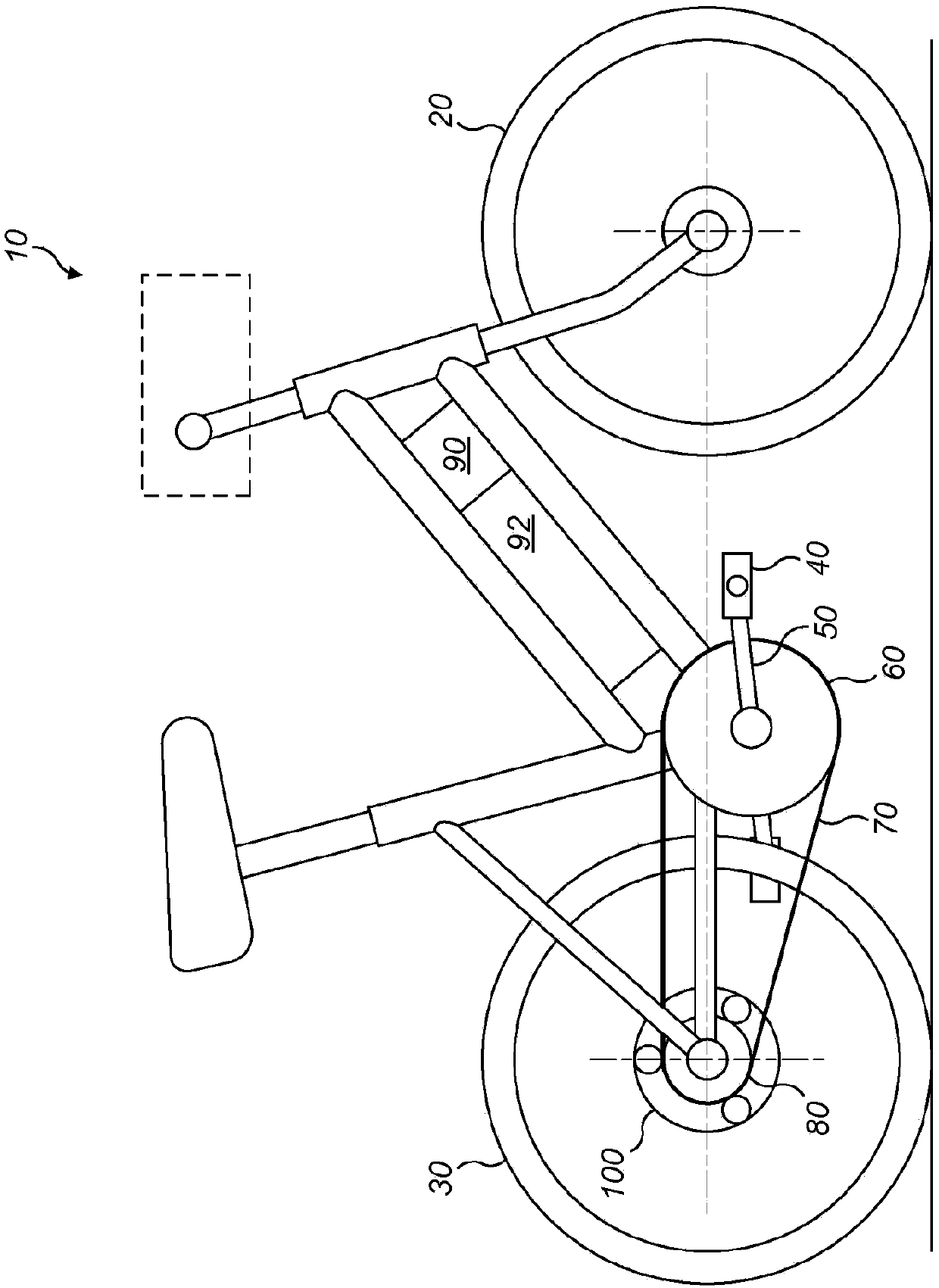
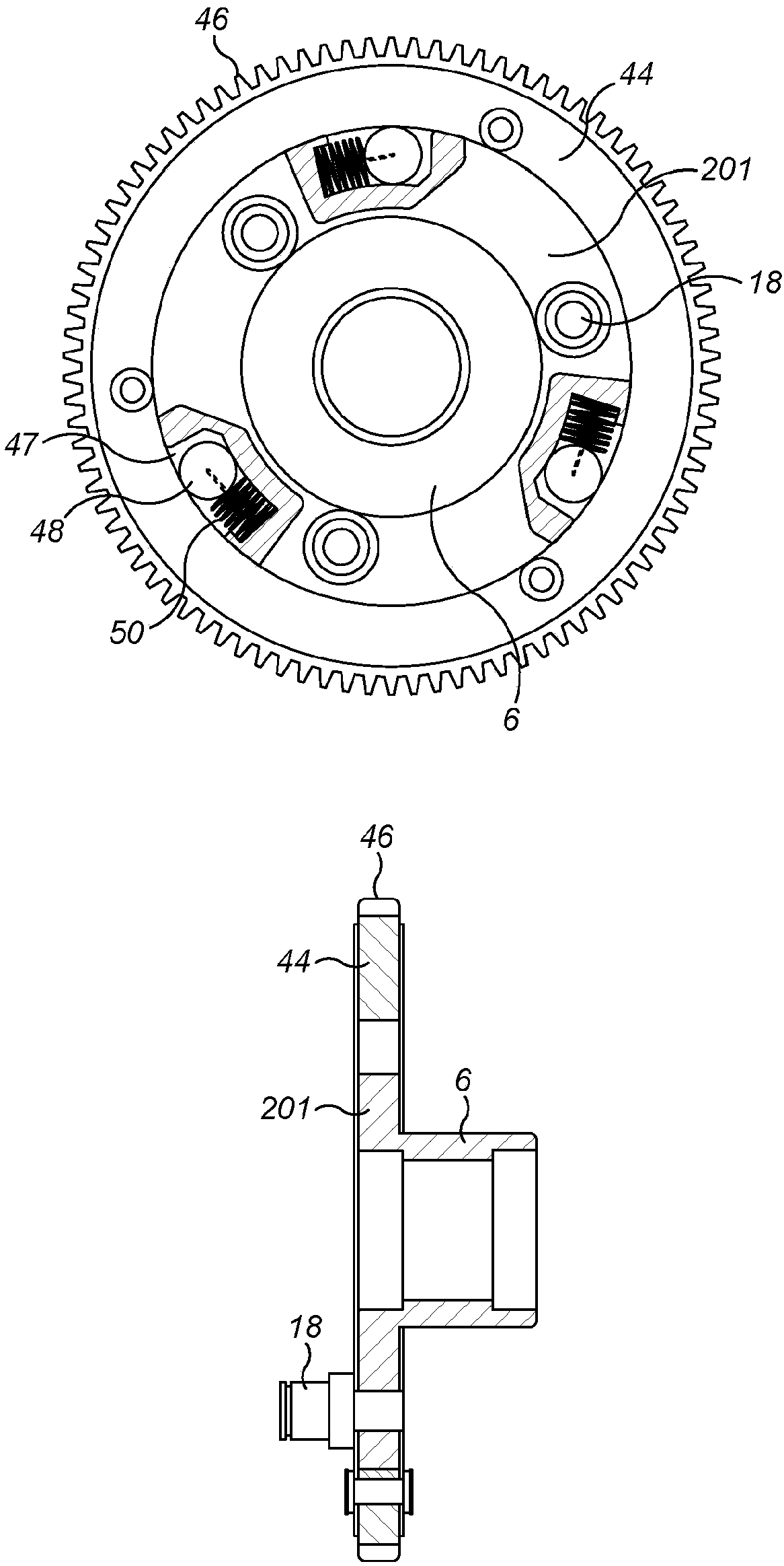
[0092] figure 1 The features shown are shared by the first and second embodiments. for Figure 2A In the first embodiment, in the second embodiment, the hub 100 is installed on the central shaft 2, and the central shaft 2 is fixedly fixed to the bicycle frame by two nuts 4 in use. The hub comprises an annular input member 6 connected via a conventional freewheel mechanism 9 to a conventional bicycle sprocket 80, not shown in detail. The input member 6 is mounted for rotation about the shaft 2 via a plurality of bearings 101 . The input member 6 is also connected to a sin...


PUM


Abstract

There is provided a method of operating a pedal cycle and a pedal cycle INC.orporating the same. The pedal cycle has an electro-mechanical drive arrangement INC.luding a continuously variable ratio transmission system having an input which is mounted to rotate about the axis and an output connected to rotate with a hub member, the transmission system comprising an epicyclic gear set INC.luding a sun gear in mesh with a plurality of planet gears mounted to rotate about respective planet shafts carried by a common carrier, which is mounted to rotate with the input about the axis, the planet gears being in mesh with an annulus gear, which is connected to rotate with the hub member. Only the sun gear may be connected to rotate a rotor of an electrical machine or an additional machine may be provided. The electrical connections of the stator of the electrical machine are connected to a controller; the method may INC.lude the step of applying a time division multiplexed control algorithm tothe electrical machine, wherein the time division multiplexed control algorithm alternates between a first control mode in which current generated by the electrical machine is monitored to infer torque applied to the crank arms of the cycle and a second control mode in which the current in the input electrical machine is controlled using the inferred torque.

Description

technical field [0001] The present disclosure relates to a method of operating a cycle having an electromechanical drive. Background technique [0002] There are various forms of bicycles. A traditional form of bicycle is one that is propelled solely by the rider applying force to its pedals, such bicycles are sometimes referred to as "push bicycles". Another newer form of bicycle is the electrically assisted bicycle (EAPC), in which electricity is used to assist or replace the rider's effort. Both traditional bicycles and EAPCs can have two, three or four wheels, and possibly more in some cases. In this document, the term "cycle" is used to include both conventional cycles and EAPCs. [0003] As mentioned above, in EAPC, electric power is used to assist or in some cases replace the cyclist's force. Thus, an EAPC comprises means for storing electrical energy, such as a battery, and an electric motor arranged for propulsion in conjunction with or instead of pedal input. ...

Claims


Application Information

Patent Timeline
IPC IPC(8): B62M6/25B62M6/50B62M6/45
CPCB62M6/25B62M6/45B62M6/50B62M6/65B62M11/16B62M6/60B62M9/06B62M11/14H02K7/116H02P5/00
Inventor 龚立楠
Owner EBIKE SYSTEMS LTD
Learn More