
Ceramic atomizing core and atomizer formed thereby

An atomizing core and atomizer technology, applied in the field of atomizers, can solve the problems of easy oil leakage, easy generation of debris in fiber cotton, high temperature resistance, etc., and achieve clean and hygienic atomization steam and good atomization taste. , the effect of simple structure

Pending Publication Date: 2018-04-06
SHENZHEN ECAP TECH CO LTD
View PDF0 Cites 9 Cited by
  • Summary
  • Abstract
  • Description
  • Claims
  • Application Information

AI Technical Summary

Problems solved by technology

[0002] Existing e-cigarette heating components are all based on fiber cotton winding heating wire, fiber cotton is prone to debris, and is not resistant to high temperature, easy to burn and affect the taste of e-cigarettes, and the existing e-cigarettes are prone to oil leakage; The atomizing tube of the existing electronic cigarette is made of metal material. The atomizing tube of the metal material is soaked in the smoke liquid for a long time, which affects the taste of the atomized steam and even affects the health.

Method used


Image

  • Ceramic atomizing core and atomizer formed thereby
  • Ceramic atomizing core and atomizer formed thereby
  • Ceramic atomizing core and atomizer formed thereby

Examples


no. 1 example

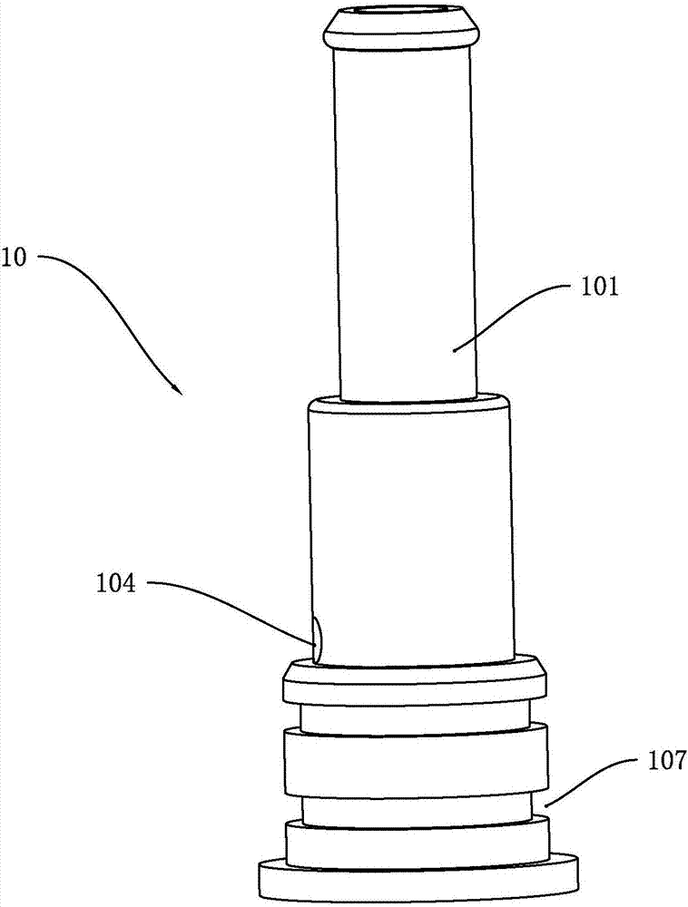
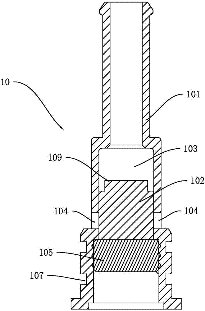
[0024] The first embodiment, such as figure 1 and figure 2 As shown, a ceramic atomizing core 10 includes a ceramic tube 101 and a microporous ceramic heating element 102. The microporous ceramic heating element 102 is located in the ceramic tube 101 and is sintered with the ceramic tube 101. The upper surface and the inner cavity of the ceramic tube 101 form an atomization chamber 103 , and the side wall of the ceramic tube 101 is provided with an oil inlet hole 104 connected with the microporous ceramic heating element 102 .

[0025] Such as figure 1 and figure 2 As shown, the external liquid passes through the oil inlet hole 104 and penetrates into the microporous ceramic heating element 102, and the microporous ceramic heating element 102 heats and atomizes the liquid. The liquid can be e-liquid. Since the microporous ceramic heating element 102 is a high-temperature-resistant material, and there is no need to add oil-conducting cotton in the ceramic atomizing core 10...

no. 3 example

[0030] The third embodiment, such as figure 1 , figure 2 and Figure 5 As shown, an atomizer includes a suction nozzle 201, a fixed seat 202, a casing 203 and an electrode assembly 211; the upper end of the casing 203 is sealed and fixedly connected with the fixed seat 202, and the fixed seat 202 penetrates an air inlet 204; the outer casing 203 The lower end is sealed and fixedly connected with the electrode assembly 211, and also includes an air guide tube 205, and a ceramic atomizing core 10. The ceramic atomizing core 10 is arranged in the shell 203 and forms an oil storage tank 206 between the inner wall of the shell 203, and one end of the air guide tube 205 Insert it into the ceramic tube 101, and the other end is docked with the suction nozzle 201. An air intake channel 207 is formed between the air guide tube 205 and the inner wall of the ceramic tube 101. External air enters from the air inlet 204 and enters the atomization chamber 103 along the air intake channel ...

no. 4 example

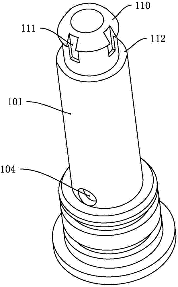
[0034] The fourth embodiment, the difference between this embodiment and the third embodiment is: if image 3 , Figure 4 and Figure 6 As shown, the atomizer also includes an annular oil sealing plug 208, the upper end of the ceramic tube 101 is inserted into the oil sealing plug 208 and the annular groove 113 of the ceramic tube 101 is in sealing connection with the inner wall of the oil sealing plug 208, and the outer wall of the oil sealing plug 208 is in contact with the oil sealing plug 208 The inner wall of the fixing seat 202 is sealed and connected. When assembling, insert the upper end of the ceramic atomizing core 10 into the oil sealing plug 208. At this time, there is a gap between the pressure relief groove 111 and the inner wall of the oil sealing plug 208, so the gas in the oil storage tank 206 can flow out from the pressure relief groove 111. The discharge prevents the air pressure from squeezing the smoke oil in the oil storage bin 206, thereby preventing t...


PUM


Abstract

The invention discloses a ceramic atomizing core and an atomizer formed thereby. The ceramic atomizing core comprises a ceramic tube and a micro-porous ceramic heating body, wherein the ceramic tube and the micro-porous ceramic heating body are sintered into a whole; an atomizing chamber is formed between the upper surface of the micro-porous ceramic heating body and the inner cavity of the ceramic tube; an oil inlet hole butted with the micro-porous ceramic heating body is formed in the side wall of the ceramic tube; the atomizer comprises a suction nozzle, a fixing seat, a shell, an electrode assembly, a gas-guide tube and the ceramic atomizing core; the upper end of the shell is fixedly sealed with the fixing seat; the fixing seat penetrates through the air inlet; the lower end of the shell is fixedly sealed with the electrode assembly; an oil storage bin is formed between the ceramic atomizing core and the inner wall of the shell; one end of the gas guide tube is inserted into theceramic tube, and the other end of the gas guide tube is butted with the suction nozzle; an air inlet channel is formed between the gas guide tube and the ceramic tube; air enters the atomizing chamber from the air inlet and the air inlet channel; and atomization steam in the atomizing chamber enters the suction nozzle along the gas guide tube. The ceramic atomizing core has the advantages of being simple in structure, oil leakage proof and clean and sanitary in atomization steam.

Description

technical field [0001] The invention relates to the technical field of atomizers, in particular to a ceramic atomization core and an atomizer composed of the same. Background technique [0002] Existing e-cigarette heating components are all based on fiber cotton winding heating wire, fiber cotton is prone to debris, and is not resistant to high temperature, easy to burn and affect the taste of e-cigarettes, and the existing e-cigarettes are prone to oil leakage; The atomizing tube of the existing electronic cigarette is made of metal material, and the atomizing tube of the metal material is soaked in the smoke liquid for a long time, which affects the taste of the atomized steam and even affects the health. Contents of the invention [0003] The purpose of the present invention is to solve the deficiencies of the prior art, and provide a ceramic atomizing core and an atomizer composed of the same. [0004] A kind of technical scheme of the present invention: [0005] A ...

Claims


Application Information

Patent Timeline
Patent Type & Authority Applications(China)
IPC IPC(8): A24F47/00
CPCA24F47/008
Inventor 廖向阳
Owner SHENZHEN ECAP TECH CO LTD
Learn More