Clamping tool for crystal cutting

A crystal cutting and clamping technology, applied in the direction of fine work equipment, work accessories, manufacturing tools, etc., can solve the problems of small contact area of ​​screws, unstable processing process, and large number of screws, etc., to achieve large clamping area, Ensure smoothness and center balance, fast clamping effect

Active Publication Date: 2018-04-06
安徽中晶光技术股份有限公司
View PDF6 Cites 1 Cited by
  • Summary
  • Abstract
  • Description
  • Claims
  • Application Information

AI Technical Summary

Problems solved by technology

[0002] After the crystal growth is completed, it needs to be processed by cutting, polishing and coating. Cutting is the first process of crystal processing. The quality of this process directly affects the subsequent processing. The existing cutting process is generally performed on a cutting machine. When the crystal needs to be clamped before cutting, the tooling used is to set a set of screws on the side wall of an empty cylinder, and the crystal is fastened and fixed by the screws. This method has the following disadvantages: the contact area of ​​the screws is small , in the process of top tightening and locking, it is easy to cause the crystal to break, the number of screws is large, the locking and fixing steps are cumbersome, the balance is poor, the crystal is easy to tilt, and the crystal is not aligned with the cutting center of the cutting machine after clamping, resulting in Instability, error-prone

Method used


Image

  • Clamping tool for crystal cutting
  • Clamping tool for crystal cutting
  • Clamping tool for crystal cutting

Examples


Embodiment Construction

[0018] In order to make the object, technical solution and advantages of the present invention clearer, the present invention will be further described in detail below in conjunction with the accompanying drawings and embodiments. It should be understood that the specific embodiments described here are only used to explain the present invention, not to limit the present invention.

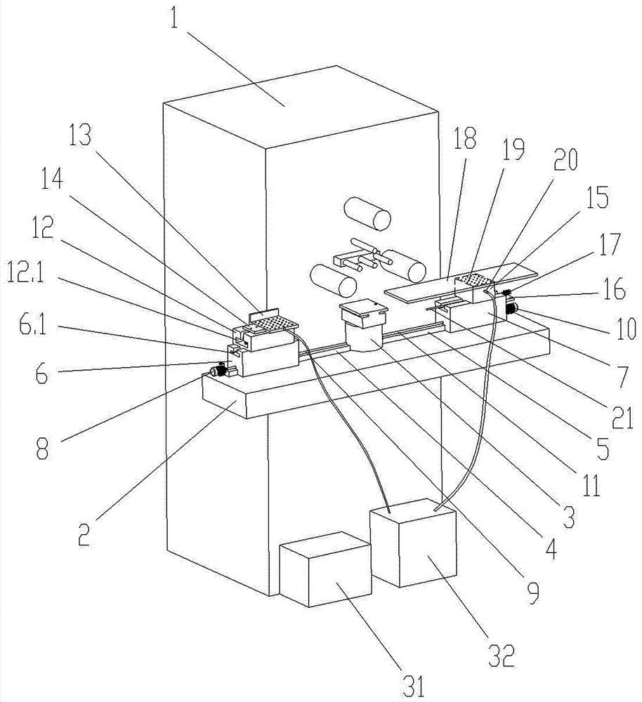
[0019] Such as figure 1 and figure 2 As shown, a clamping tool for crystal cutting provided by the present invention includes a square bottom plate 1. When in use, the bottom plate 1 is installed on the fixing seat of the cutting machine, and a circle is arranged at the center of the upper side of the bottom plate 1 Shaped grooves, in the grooves are fixedly connected to the fixed cylinder 2 by adhesive bonding.

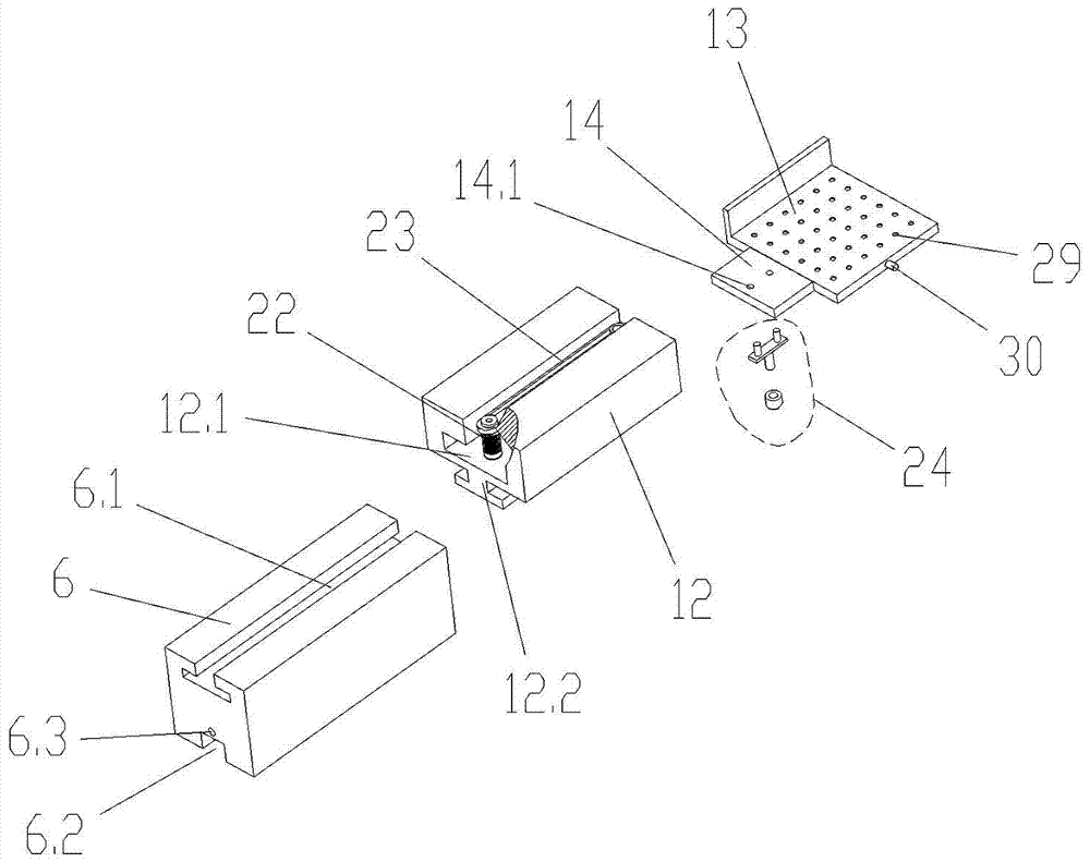
[0020] The fixed cylinder 2 is a circular bobbin structure, three open slots 3 are evenly distributed on the upper side of the fixed cylinder 2, and a plug-in plate 6 is snapped into e...


PUM


Abstract

The invention discloses a clamping tool for crystal cutting. The clamping tool comprises a bottom plate; the bottom plate is connected with a fixing barrel; the fixing barrel is connected with plugboards in the clamping manner; the plugboards are connected with oscillating rods through knuckle bearings; the inner sides of the oscillating rods are hinged to clamping plate devices; electric push rods are arranged on the bottom plate, and are in lifting connection with a backing plate; a pressure-sensitive switch is arranged on the upper side surface of the backing plate; the outer side of the fixing barrel is sleeved and connected with fixing rings; the fixing rings are connected with revolving rings; the outer sides of the revolving rings are sleeved and connected with toothed rings; an upright rod is uniformly arranged on the upper side of each revolving ring; each upright rod is connected with the corresponding oscillating rod; motors are arranged on the bottom plate and are connectedwith gears; and the gears are engaged with the toothed rings. The clamping tool has the advantages that the clamping tool is high in clamping speed, so that a clamped crystal is located in the centerof the fixing barrel and cannot incline; and clamping plates are in soft contact with the crystal and the clamping area is large, so that a previous crystal breaking situation is avoided, and the surface smoothness of the crystal, the center balance of the crystal and the operational stability are ensured.

Description

technical field [0001] The invention relates to the technical field of crystal processing, in particular to a clamping tool for crystal cutting. Background technique [0002] After the crystal growth is completed, it needs to be processed by cutting, polishing and coating. Cutting is the first process of crystal processing. The quality of this process directly affects the subsequent processing. The existing cutting process is generally performed on a cutting machine. When the crystal needs to be clamped before cutting, the tooling used is to set a set of screws on the side wall of an empty cylinder, and the crystal is fastened and fixed by the screws. This method has the following disadvantages: the contact area of ​​the screws is small , in the process of top tightening and locking, it is easy to cause the crystal to break, the number of screws is large, the locking and fixing steps are cumbersome, the balance is poor, the crystal is easy to tilt, and the crystal is not ali...

Claims


Application Information

Patent Timeline
IPC IPC(8): B28D5/00B28D7/00B28D7/04
CPCB28D5/00B28D5/0058B28D5/0082
Inventor 胡治军
Owner 安徽中晶光技术股份有限公司
Why Eureka
Try Eureka