Cutting mechanism of window patching machine

A window sticking machine and cutting technology, which is applied in the direction of container manufacturing machinery, rigid/semi-rigid container manufacturing, paper/cardboard containers, etc., can solve the problem that the sticking position cannot meet the qualified requirements and affect the adsorption position of the lower roller, etc. Problems, to achieve the effect of improving the qualified rate and ensuring the processing accuracy

Pending Publication Date: 2018-04-06
袁新国
View PDF0 Cites 1 Cited by
  • Summary
  • Abstract
  • Description
  • Claims
  • Application Information

AI Technical Summary

Problems solved by technology

[0002] The cutting mechanism of the existing window sticking machine is generally to install the upper cutter on the upper roller, the adsorption component is arranged on the lower roller, and the lower cutter is separately provided with a mechanism to cooperate with the upper cutter to cut off the film. Part of it is not adsorbed on the lower roller, and will be slightly displaced when it is cut, which will affect the adsorption position on the lower roller, resulting in the subsequent sticking position often failing to meet the qualified requirements

Method used


Image

  • Cutting mechanism of window patching machine
  • Cutting mechanism of window patching machine
  • Cutting mechanism of window patching machine

Examples


Embodiment 1

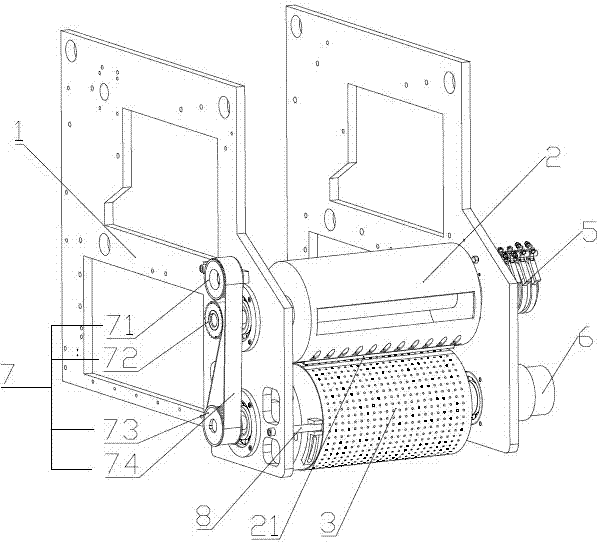
[0027] Embodiment 1: The cutter assembly includes an upper cutter 21 fixed on the outer peripheral surface of the upper roller 2 in the axial direction, and an upper cutter 21 arranged on the outer peripheral surface of the lower roller 3 and cutting off the uncut blade together with the contact. Cut the hard surface of the film, the lower roller 3 is provided with a hard strip 31 corresponding to the upper cutter 21, and the hard strip 31 is embedded in the outer circumference of the lower roller 3 along the axial direction, so The hard strip 31 has an arc surface and is flush with the circumferential surface of the lower roller 3. The hard strip 31 is made of hard alloy material. The advantage of the first embodiment is that the material cost is saved. When the upper cutter and the hard strip rotate The synchronization requirements are high.

Embodiment 2

[0028] Embodiment 2: The cutter assembly includes an upper cutter 21 fixed on the outer peripheral surface of the upper roller 2 in the axial direction, and an upper cutter 21 arranged on the outer peripheral surface of the lower roller 3 and cutting off the uncut material together with the contact. Cutting the hard surface of the film, the lower roller 3 is made of hard alloy material as a whole, which has the advantage of not requiring high synchronization of the transmission mechanism. The upper roller and the lower roller can have their own power components, and can also realize The effect of embodiment one.

Embodiment 3

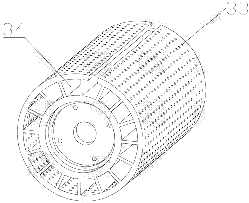
[0029] Embodiment 3: The cutter assembly includes an upper cutter 21 fixed on the outer peripheral surface of the upper roller 2 in the axial direction, and an upper cutter 21 arranged on the outer peripheral surface of the lower roller 3 and cutting off the uncut blade together with the contact. Cut the hard surface of the film, the outer circumference of the lower roller 3 is wrapped with a hard layer 32 made of cemented carbide material and with several through holes, the through holes of the hard layer correspond to the air suction holes on the lower roller , the advantages of the third embodiment are similar to those of the second embodiment, but the use of materials is less than that of the second embodiment, and the effect of the first embodiment can be achieved.

[0030] The other end of the upper roller 2 is provided with an electric heating element 5 that transfers heat to the upper cutter 21 through the upper roller 2. The inside of the upper roller 2 is hollowed out...


PUM


Abstract

The invention discloses a cutting mechanism of a window sticking machine, which relates to the field of window sticking processing equipment, and solves the problem of displacement after cutting. An upper roller and a lower roller, the lower roller is provided with an adsorption assembly for attaching the film to be cut to its outer peripheral surface, and the upper roller and the lower roller are provided with a The cutter assembly is used for precise cutting without displacement and adsorption, and a distance between the upper roller and the lower roller is provided to ensure the normal operation of the cutter assembly. The invention has the advantages of stable cutting and high qualified rate.

Description

technical field [0001] The invention relates to the field of window pasting processing equipment, in particular to a cutting mechanism of a window pasting machine. Background technique [0002] The cutting mechanism of the existing window sticking machine is generally to install the upper cutter on the upper roller, the adsorption component is arranged on the lower roller, and the lower cutter is separately provided with a mechanism to cooperate with the upper cutter to cut off the film. A part is not adsorbed on the lower roller, and will be slightly displaced when being cut, thereby affecting the adsorption position on the lower roller, causing the subsequent sticking position to often fail to meet the qualified requirements. Contents of the invention [0003] In order to overcome the shortcomings of the background technology, the present invention provides a cutting mechanism of a window pasting machine with stable cutting and high pass rate. [0004] The technical sol...

Claims


Application Information

Patent Timeline
Patent Type & Authority Applications(China)
IPC IPC(8): B31B50/20
Inventor 袁新国
Owner 袁新国
Why Eureka
Try Eureka