Oil tube clamping and positioning device

A clamper and tubing technology, which is used in wellbore/well components, earthwork drilling, etc., can solve problems such as the lack of universality of the clamper

Active Publication Date: 2018-04-06
PETROCHINA CO LTD
View PDF3 Cites 2 Cited by
  • Summary
  • Abstract
  • Description
  • Claims
  • Application Information

AI Technical Summary

Problems solved by technology

[0004] In order to solve the problem of poor versatility of existing locking devices, the embodiment of the present invention provides a tubing locking device

Method used


Image

  • Oil tube clamping and positioning device
  • Oil tube clamping and positioning device
  • Oil tube clamping and positioning device

Examples


Embodiment

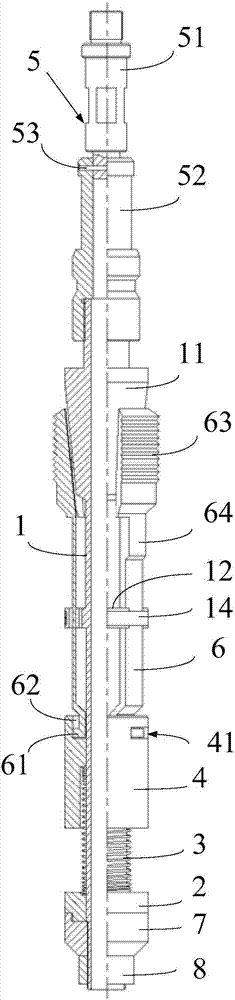
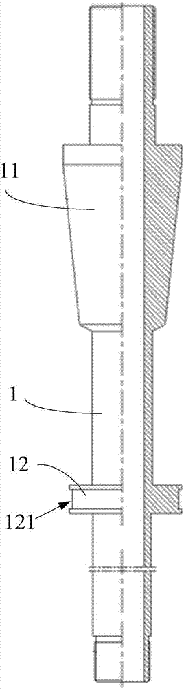
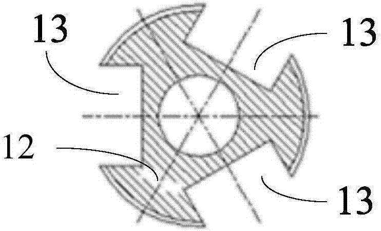
[0026] The embodiment of the present invention provides an oil pipe retainer, such as figure 1 As shown, the tubing retainer includes a central tube 1, a temperature-controlled magnetic steel 2, an elastic member 3, a slip seat 4, a fishing assembly 5 and three slips 6, and the temperature-controlled magnetic steel 2 is fixedly set on the central tube 1. The bottom of the bottom, the slip seat 4 is a ferromagnetic member, the slip seat 4 is slidably set on the central tube 1 and is located above the temperature control magnet 2, and the elastic member 3 is arranged on the slip seat 4 and the temperature control magnet 2 Between them, the three slips 6 are equidistantly arranged in the circumferential direction with the center tube 1 as the central axis, and the bottoms of the three slips 6 are all movably clamped with the top of the slip seat 4, and the outer peripheral wall of the center tube 1 corresponds to The position of the top of the slips 6 is provided with a frustum 1...


PUM


Abstract

The invention discloses an oil tube clamping and positioning device, and belongs to the field of oilfield exploitation equipment. The oil tube clamping and positioning device comprises a central tube,temperature control magnetic steel, an elastic piece, a slip bowl, a dropping-fishing assembly and at least two slips, wherein the bottom of the central tube is fixedly sleeved with the temperature control magnetic steel; the slip bowl is a ferromagnetic component, the central tube is sleeved with the slop bowl in a sliding mode, and the slip bowl is located above the temperature control magneticsteel; the elastic piece is arranged between the slip bowl and the temperature control magnetic steel; the slips are circumferentially arranged with the central tube as an axis at equal intervals, and the bottoms of the slips are movably clamped to the top of the slip bowl; a frustum is arranged at the positions, corresponding to the tops of the slips, of the peripheral wall of the central tube,and the diameter of the end surface, close to the slip bowl, of the frustum is smaller than that of the other end surface of the frustum; the dropping-fishing assembly comprises a shearing pin, a dropping head and a fishing head, the dropping head is used for being connected with a hoisting steel wire, the fishing head is used for being fixedly installed on the top of the central tube, and the shearing pin is arranged between the dropping head and the fishing head. According to the oil tube clamping and positioning device, the applicability of the oil tube clamping and positioning device is improved.

Description

technical field [0001] The invention belongs to the field of oil field exploitation equipment, in particular to an oil pipe clamping device. Background technique [0002] The tubing clamp is a downhole device used to lock the inner wall of the tubing, and is usually used in the plunger gas lift process. [0003] When using the tubing clamp, it is necessary to lower the tubing clamp from the wellhead to the downhole. However, the pipes of the gas tree at the wellhead and the tubing downhole sometimes use different pipe diameters. For gas wells that can only be put into production after artificial hydraulic fracturing, in order to improve the effect of fracturing, oil pipes with larger diameters (larger than the 65mm diameter gas trees commonly used in China) are often used, which leads to the possibility of lowering the gas wells from the wellhead. The specification of the clamping device is not enough to be clamped on the inner wall of the downhole tubing, and the specifica...

Claims


Application Information

Patent Timeline
Patent Type & Authority Applications(China)
IPC IPC(8): E21B23/01
Inventor 周贤杜立红段宝玉段冉叶其军甘运才吴天春
Owner PETROCHINA CO LTD
Why Eureka
Try Eureka