Optical detection equipment

An optical detection and equipment technology, applied in the field of optical detection equipment, can solve the problems of large subjective judgment factors, low efficiency, and unguaranteed quality, and achieve the effects of convenient and fast adjustment, increased installation space, and high installation position

Pending Publication Date: 2018-04-06
ZHEJIANG SUNNY OPTICAL CO LTD
View PDF6 Cites 0 Cited by
  • Summary
  • Abstract
  • Description
  • Claims
  • Application Information

AI Technical Summary

Problems solved by technology

At present, optical lenses mainly use plastic aspheric lenses or Fresnel lenses, and use injection molding technology to detect the quality of existing VR lens imaging, and use human eyes to observe the experience, which is subj

Method used


Image

  • Optical detection equipment
  • Optical detection equipment
  • Optical detection equipment

Examples


Embodiment approach

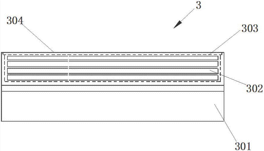
[0051] image 3A side view of a target according to the invention is schematically represented. According to an embodiment of the present invention, the target 3 includes a casing 301 , a light source 302 , a light source diffusion plate 303 and a target plate 304 . In this embodiment, the target plate 304, the light source diffusion plate 303 and the light source 302 are arranged in order from top to bottom, the target plate 304 and the housing 301 form a closed space, and the light source 302 and the light source diffusion plate 303 are located 301 in the confined space formed. The light source 302 adopts an LED annular uniform light source, and the target plate 304 is a film target plate with vertical and horizontal lines.

[0052] Figure 4 Schematic representation of a perspective view of a black box that can accommodate an optical detection device according to the invention. According to an embodiment of the present invention, the black box 6 is a square hollow box a...


PUM


Abstract

The invention relates to optical detection equipment which comprises a supporting mechanism, an image collecting mechanism movably carried on the supporting mechanism, a target located next to the supporting mechanism and below the image collecting mechanism, a lens carrying device located between the image collecting mechanism and the target and a bearing mechanism located next to the target forbearing the lens bearing device and being capable of adjusting the position of the lens bearing device, wherein the supporting mechanism, the target and the supporting mechanism are successively arranged from left to right. The optical detection equipment is simple in structure, convenient and rapid in detection process, high in detection precision and low in cost.

Description

technical field [0001] The invention relates to an optical detection device, in particular to an optical detection device for detecting a virtual reality (Virtual reality) lens. Background technique [0002] Chinese patent 201510424415.6 discloses a grating-modulated lens defect automatic detection device and method. The lens defect automatic detection device modulated by the grating includes an image acquisition device, a camera fixing frame, a lens fixing frame, a grating, a linear screw guide rail, a plane backlight source and the like. In this grating modulation automatic detection device for lens defects, the image acquisition device is installed on the camera fixed frame, and the image acquisition device can only move along the lateral translation on the camera fixed frame. At the same time, the lens holder cannot be moved, and the position of the detected lens on the lens holder is fixed. The grating is installed on the linear screw guide rail and can only move alon...

Claims


Application Information

Patent Timeline
IPC IPC(8): G01N21/958
CPCG01N21/958G01N2021/9583Y02E10/50
Inventor 计其林刘文迪
Owner ZHEJIANG SUNNY OPTICAL CO LTD
Why Eureka
Try Eureka