Bi-directional piston double row type high efficiency pump device for agricultural chemical sprayer

A two-way piston and sprayer technology, applied in piston pumps, components of pumping devices for elastic fluids, pumps, etc., can solve problems such as large production costs, and achieve the effects of improved performance, strong performance, and convenient assembly and combination.

Inactive Publication Date: 2018-04-06
朴俊赫
8 Cites 4 Cited by

AI-Extracted Technical Summary

Problems solved by technology

[0017] The use of large-capacity molds will inevitably require huge production cos...

Method used

[0046] In addition, the cylinder 700 is usually separated from the outer casing and is formed separately with a certain diameter and length. It is different from the overall design of the cylinder in the outer casing. The for...

Abstract

The present invention relates to a bi-directional piston double-line type high efficiency pump device for an agricultural chemical sprayer, in which a pumping operation by means of a piston is conducted in a bi-directional double row when agricultural chemicals are sprayed, thereby maximizing efficiency. In addition, the device can be easily manufactured and assembled, and the device enables a high performance pumping operation at a lower cost. Specifically, the present invention is configured as follows: a shaft installation space part (110) is formed in the inner center of a housing body (100), both sides of which are formed to INC.lude pumping operation chambers (120), and a plurality of cylinder communication grooves are formed in each of the pumping operation chambers (120) at the right and left sides; a plurality of eccentric cam wheels (210) are formed in a multi-stage manner at a rotation shaft (200) installed in the shaft installation space part (100) of the housing body (100); upper and lower link units (300) having rod connection parts (330) of different directions are coupled in each of the cam wheels (210); the rod connection parts (330) each comprise a piston rod (400) and a piston (410); and a cylinder fixing unit (500), a pumping cylinder (700) and a cylinder cap unit (600) are assembled and coupled by means of a batch fixing means (800) outside the pumping operation chambers (120) at the right and left sides of the housing body (100), in which a plurality of pumping operation chambers (120) are formed.

Application Domain

Technology Topic

Image

  • Bi-directional piston double row type high efficiency pump device for agricultural chemical sprayer
  • Bi-directional piston double row type high efficiency pump device for agricultural chemical sprayer
  • Bi-directional piston double row type high efficiency pump device for agricultural chemical sprayer

Examples

  • Experimental program(1)

Example Embodiment

[0028] Below in conjunction with accompanying drawing, the present invention is described in further detail:
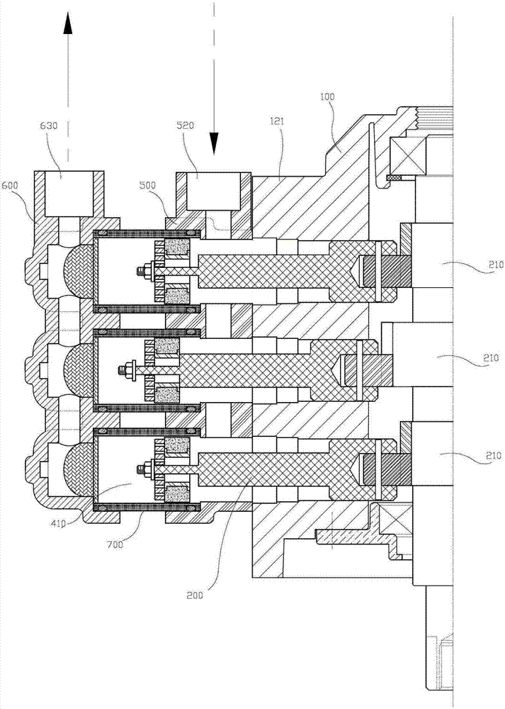
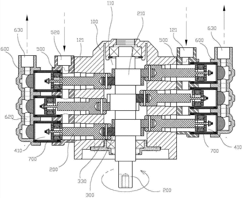
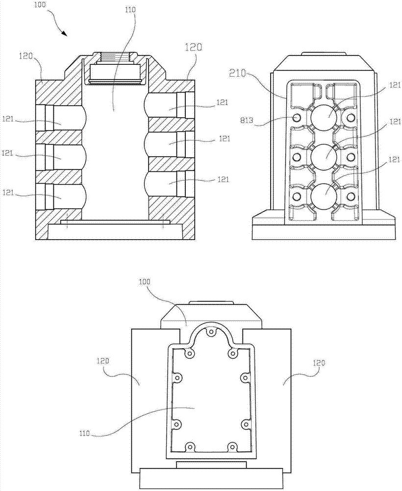
[0029] A two-way piston high-efficiency pump for a pesticide sprayer, in which a shaft installation space 110 is formed in the center of the outer casing 100 . The pumping operation chambers 120 on the left and right sides of the shaft installation space 110 are integrally formed with the outer casing 100, respectively. Each of the pumping operation chambers 120 on the left and right sides is provided with a cylinder communication groove 121 that communicates with the shaft installation space 110 outward, and a plurality of them are arranged at certain intervals;
[0030] In the present invention, a drive motor (not shown) is provided in the shaft installation space 110 of the outer casing 100 to drive the rotation shaft 200 to rotate vertically. Multiple sets of eccentric wheels 210 on the rotating shaft 200 are arranged and installed at intervals;
[0031] Two sets of tightly combined rings 320 are sleeved on each of the above-mentioned eccentric wheels 210, and a rod connecting part 330 protrudes from the side of the ring 320 in one direction, and the connecting parts on the two sets of tightly combined rings are respectively arranged on both sides of the eccentric wheel , forming the upper and lower connection units 300, the rod connection part 330, the upper connection unit 300 and the lower connection unit 300 become a combination formed in opposite directions;
[0032] According to the operating rules of the eccentric wheel 210, the rod connecting parts 330 formed on the left and right sides are respectively corresponding to the positions of a plurality of cylinder communication grooves 121, and the piston rod 400 and the piston rod 400 which can perform left and right reciprocating movements are connected inside the cylinder connecting grooves. Piston 410;
[0033] The pumping operation chamber 120 on the left and right sides of the outer casing 100 formed by a plurality of pumping operation chambers 120 is installed with a cylinder fixing unit 500 corresponding to the pumping cylinder 700;
[0034] On the other hand, the cylinder head unit 600 is connected to the outer end of the pumping cylinder 700 .
[0035] With a fixed interval, a plurality of groups of cylinders each having a constant diameter are installed between the cylinder fixing unit 500 and the cylinder head unit.
[0036] The pumping operation chamber is installed with a cylinder fixing unit 500 , a cylinder 700 , and a cylinder head unit 600 sequentially through a fixing device 800 on the outside of the pumping operation chamber 120 on the left and right sides of the outer casing 100 .
[0037] The eccentric wheel 210 formed on the rotating shaft 200 in the above structure is just because its center is constantly deviated from the center of the rotating shaft 200, and a plurality of eccentric wheel shafts with certain intervals are formed on the rotating shaft 200, so when one of the eccentric wheel shafts follows the When the rotating shaft 200 rotates, the other eccentric wheels 210 can rotate simultaneously.
[0038] The upper connection unit 300 and the lower connection unit on the same eccentric wheel 210 are connected to each other, so that the direction of the rod connection part 330 is different from that of the eccentric wheel 210, and when one eccentric wheel 210 operates, the rods in both directions are connected The part 330 can alternately reciprocate.
[0039] At this time, if figure 1As shown, the upper and lower connection units 300 are wrapped around one side or the other side of the connection of the eccentric wheel 210 through the ring 320, and a pin fixing groove 331 is provided at the head of the rod connection part, so that the rod connection part can be inserted into the piston rod One end of 400 is fixedly connected through the pin fixing groove 331 .
[0040] In addition, one end of the piston rod is provided with an assembly unit 402, in which a rod insertion groove 401 for inserting the rod connecting portion 330 into one end of the piston rod is formed, and then fixed by inserting a pin into the pin fixing groove 331, the piston 410 is mounted on the piston rod the other end of the
[0041] The above-mentioned piston 410 moves back and forth in the cylinder 700 with the movement of the piston rod 400 as mentioned above, and plays an important role in pumping water.
[0042] The other end of the piston rod 400 is formed with a piston fastening thread 411, and the piston fastening thread 411 penetrates into the washer 412, and the rubber washer 413b surrounds the outer side of the metal ring 413a, and the two are integrally formed into a rubber sealing part 413, and are located at On the top of the washer member 412, a perforation stop member 414 with several small through holes 414a is installed on the top of the rubber sealing part 413, and finally the nut 415 is covered on the top of the perforation stop member, and screwed and fastened on the piston fastening The end of thread 411.
[0043] The gap between the bottom surface of the piston fastening thread 411 and the nut 415 is larger than the thickness of the washer 412, the rubber seal part 413 and the piercing stop member 414, so that it can be kept loose.
[0044] When pushing (pumping) for pumping water, the rubber sealing member 413 is in close contact with the perforation stop member 414, and the liquid medicine cannot pass through, and when it is backward (pulling), the rubber sealing member 413 passes through the groove inside. There is a gap between 413c and the through hole 414a on the perforation stop member 414, so that the liquid medicine can flow through smoothly.
[0045] Therefore, the liquid medicine is completely sealed when the piston 410 moves forward to achieve high-pressure pumping and pumping. On the contrary, the liquid medicine pumped into the object can be continuously sucked and compressed in the cylinder when the piston 410 moves backward.
[0046] In addition, the cylinder 700 is usually separated from the outer casing and formed separately with a certain diameter and length, which is different from the overall design of the cylinder in the outer casing. The former can be processed and produced separately, and the assembly structure can be installed after the processing is completed. Compared with the compact machining of the cylinder, the method is simpler and cheaper.
[0047] The cylinder fixing unit 500 is formed with several dry through holes 510 for allowing the piston rod 400 to pass through, and a communication hole 520 is formed between adjacent through holes for communicating the two for passing the medicinal liquid.
[0048] In addition, the cylinder head unit 600 is connected to the cylinder end of the cylinder fixing unit 500 at a predetermined distance from the cylinder fixing unit 500, the cylinder fixing groove 601 is formed on the cylinder side inside the cylinder head unit 600, and the inside of the cylinder fixing groove is formed There are a plurality of output space parts 610 for discharging the pumped high-pressure water to the outside, channels 620 are also arranged between the plurality of output space parts, and in the output space part 610, there are liquid discharge ports 630 for discharging medicinal liquid. Set at the head position or tail position on the side of the output space portion 610 .
[0049] In addition, the high-pressure chemical liquid drawn (pumped) from the cylinder 700 cannot return to the cylinder, but can only be discharged to the liquid discharge port 630 in the output space part 610 of the cylinder head unit 600, so the output space part 610 must be built-in. return valve.
[0050] The pumping operation chamber of the above-mentioned fixing device 800 is assembled in the side wall of each pumping operation chamber 120 on the left and right sides of the outer casing 100, as a device for simultaneously fixing the cylinder fixing unit 500, the cylinder 700 and the cylinder head unit 600,
[0051] Fixing brackets 810 having a plurality of fixing holes 811 are installed and formed on both sides of the cylinder head unit 600 .
[0052] Pumping Operation Chamber A threaded hole 812 corresponding to the fixing hole 811 is provided on the side wall of the pumping operation chamber 120 .
[0053] Between the plurality of fixing holes 811 of the above-mentioned cylinder unit 600 and the plurality of threaded holes 812 formed on the surface of the above-mentioned pumping operation chamber 120, the long fixing bolts 813 are used to firmly fix. plan to complete the implementation.
[0054] Symbol Description
[0055] 100: Outer body shell 110: Power distribution container
[0056] 120: Pumping operation room 121: Cylinder communication groove
[0057] 200: rotating shaft 210: first driven shaft
[0058] 320: ring 300: upper and lower connection unit
[0059] 330: rod connection part 400: piston rod
[0060] 500: cylinder fixing unit 600: cylinder head unit
[0061] 700: Cylinder for pumping water 800: Fixing device

PUM

no PUM

Description & Claims & Application Information

We can also present the details of the Description, Claims and Application information to help users get a comprehensive understanding of the technical details of the patent, such as background art, summary of invention, brief description of drawings, description of embodiments, and other original content. On the other hand, users can also determine the specific scope of protection of the technology through the list of claims; as well as understand the changes in the life cycle of the technology with the presentation of the patent timeline. Login to view more.

Similar technology patents

Classification and recommendation of technical efficacy words

  • Reduce manufacturing cost
  • Simple structural design

A graphic OSD controller integrated into video processing chip

InactiveCN101150682AReduce storage space requirementsSimple structural designTelevision system detailsColor television detailsWork patternBitmap
Owner:XI AN JIAOTONG UNIV
Why Eureka
Try Eureka