Robot hand and transporting robot

A robot arm and robot technology, applied in the field of conveying robots, can solve problems such as impossible to enter the box, thickening of the thickness, and the inability of the robot arm to enter the box.

Active Publication Date: 2018-04-10
DISCO CORP
View PDF10 Cites 3 Cited by
  • Summary
  • Abstract
  • Description
  • Claims
  • Application Information

AI Technical Summary

Problems solved by technology

However, such a robot arm needs to eject a large amount of air, and the thickness of the robot arm is increased to increase the flow path through which the air circulates in the robot arm, so the robot arm may not be able to enter the box.
In addition, for example, in the invention of Japanese Patent No. 4299111, the holding part enters the case, but since the thickness of the robot arm is thick, it is impossible to enter the case when the thickness of the wafer becomes thicker.

Method used


Image

  • Robot hand and transporting robot
  • Robot hand and transporting robot
  • Robot hand and transporting robot

Examples


Embodiment Construction

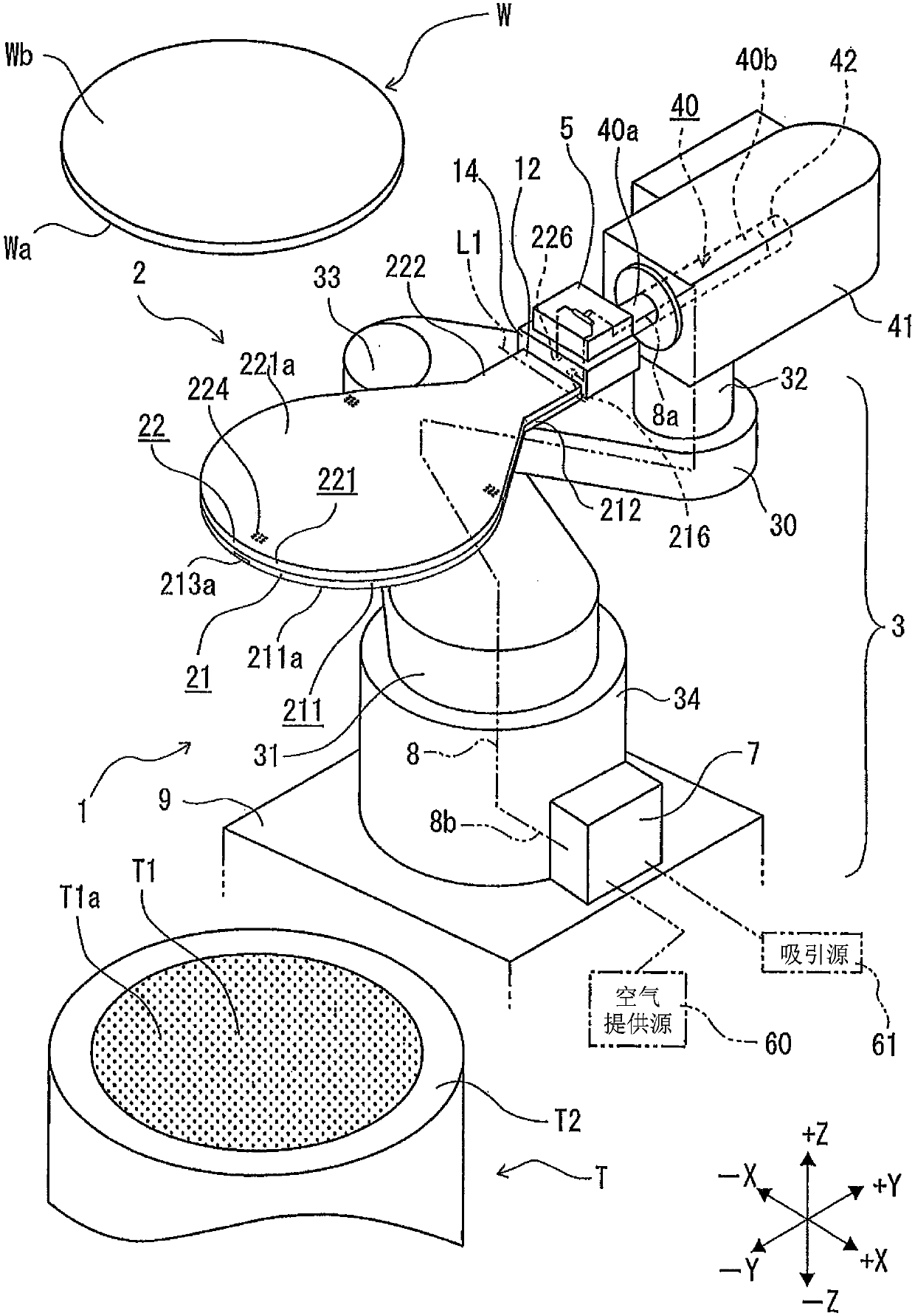
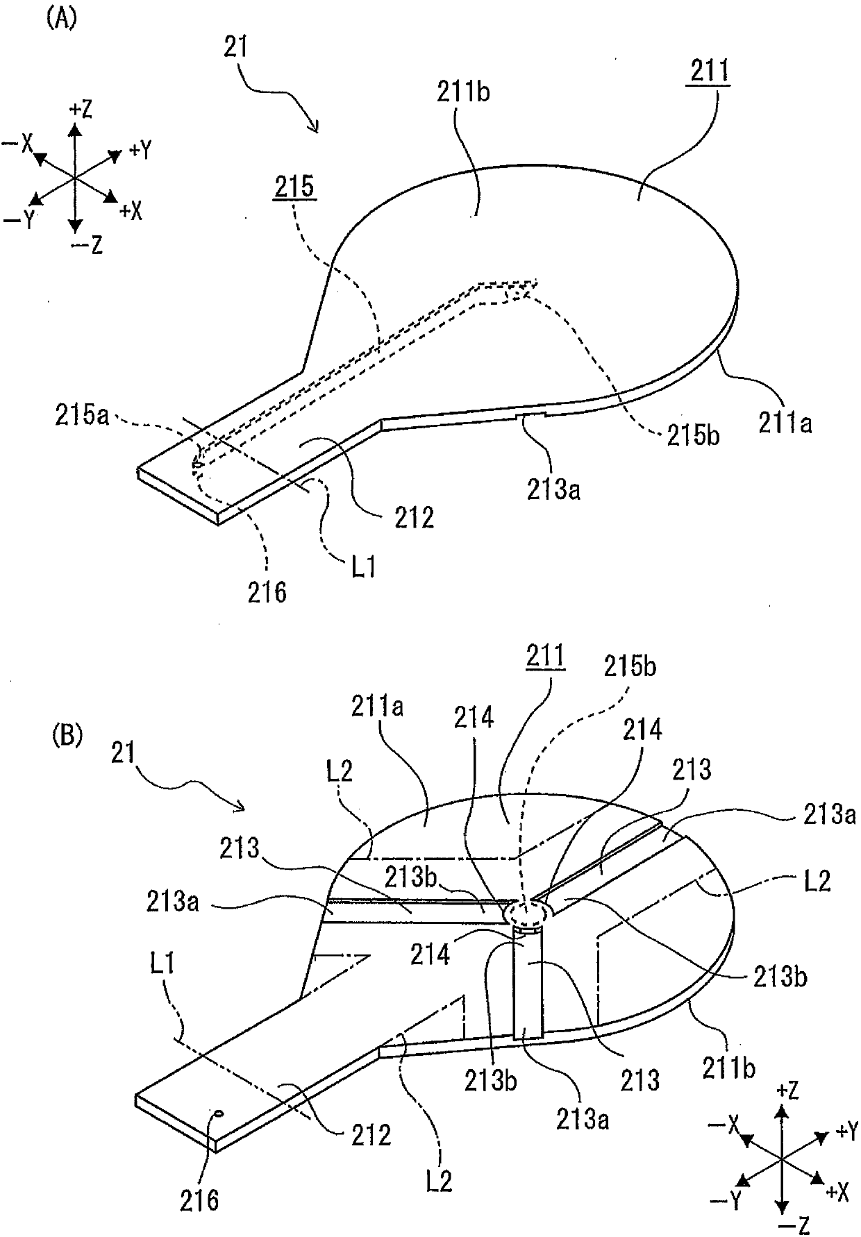
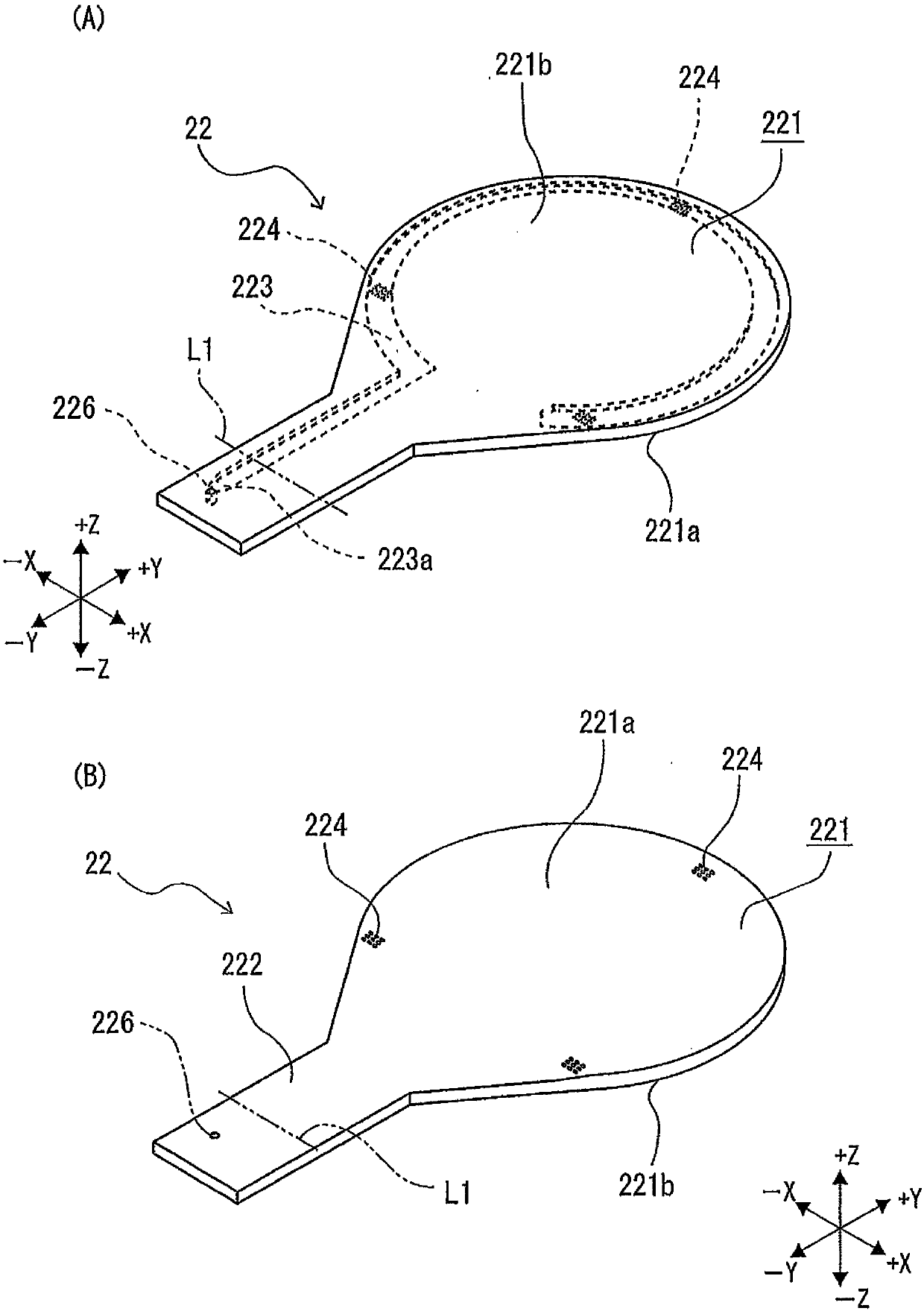
[0026] figure 1 The transfer robot 1 shown is arranged, for example, on a grinding machine not shown, and performs the following operations: carrying out a wafer W stored in a cassette in the shape of a shelf from the cassette, or using a plate-shaped robot arm 2 to place the wafer W on the cassette. W is held and stored in a box, or transported to a holding table T. The plate-shaped robot arm 2 included in the transfer robot 1 has: one surface 211a for suction-holding the wafer W in a non-contact manner; the other surface 221a for suction-holding the wafer; 12.

[0027] figure 1 The illustrated wafer W is, for example, a circular plate-shaped semiconductor wafer. A plurality of devices are formed on the front Wa of the wafer W. For example, a protective tape (not shown) is attached to the front Wa to protect the front Wa. The back surface Wb of the wafer W is a surface to be processed on which grinding or the like is performed.

[0028] figure 1 The robot arm 2 shown has...


PUM


Abstract

The present invention prevents the debris from adhering to the robot hand. A plate-shaped robot hand 2 has a first holding means 21 for causing air to flow along one face 211a to perform noncontact suction holding of the wafer and a second holding means 22 for holding the wafer on the other face 221a by suction. The holding means 21 includes a first plate member 211; a groove 213 formed on one surface 211a and one end of which opens to the outer periphery of the plate member 211; an jet port 214 for jetting air from the other end of the groove to one end; and a a supply path 215 formed in theholding means and communicating the jet port with a first connection port 216 of an attachment portion 12. The holding means 22 includes a second plate member 221; a suction port 224 for communicatingthe other surface with a suction source 61; and a suction port 223 formed inside the holding means for communicating the suction port 224 and a second connection port 226 provided in the attachment portion 12 attached to the robot 1.

Description

technical field [0001] The present invention relates to a robot arm for holding a wafer on a processing device or the like, and a transfer robot for holding the wafer by the robot arm and transferring the wafer. Background technique [0002] In a processing device such as a cutting device or a grinding device that processes semiconductor wafers, for example, a plate-shaped workpiece is taken out from the inside of the cassette placed on the cassette stage and transported to the holding table, or when the processing of the plate-shaped workpiece is completed Thereafter, the processed plate-shaped workpiece is stored in a box. In addition, a transfer robot for taking out wafers from the cassette or storing wafers in the cassette is disposed in the processing apparatus, and the transfer robot has a robot arm having a holding surface for sucking and holding the wafer on one surface. (For example, refer to Patent Document 1). [0003] Patent Document 1: Japanese Patent Laid-Ope...

Claims


Application Information

Patent Timeline
IPC IPC(8): B25J11/00B25J15/06
CPCB25J11/00B25J11/0095B25J15/0616H01L21/67742H01L21/6838
Inventor 中塚敦
Owner DISCO CORP
Why Eureka
Try Eureka