
A kind of egr system and its control method

A control valve and a part of the technology, applied in the direction of charging system, engine control, machine/engine, etc., can solve the problems that the degree of improvement depends on the performance of the supercharger, the difficulty of increasing the EGR rate of the EGR system, and the difficulty in achieving the EGR rate, etc., to achieve The effect of constant pressure boost and high EGR rate

Active Publication Date: 2020-06-02
WEICHAI POWER CO LTD
View PDF3 Cites 0 Cited by
  • Summary
  • Abstract
  • Description
  • Claims
  • Application Information

AI Technical Summary

Problems solved by technology

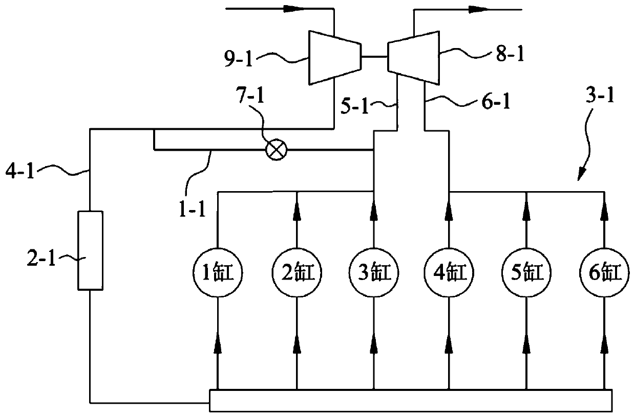
[0007] An object of the present invention is to provide an EGR system to solve the problem that the EGR rate of the EGR system in the prior art is difficult to increase, it is difficult to achieve a higher EGR rate, and the degree of increase depends on the performance of the supercharger itself

Method used


Image

  • A kind of egr system and its control method
  • A kind of egr system and its control method
  • A kind of egr system and its control method

Examples


Embodiment Construction

[0057] The technical solutions of the present invention will be further described below in conjunction with the accompanying drawings and through specific implementation methods.

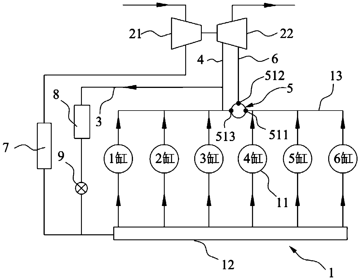
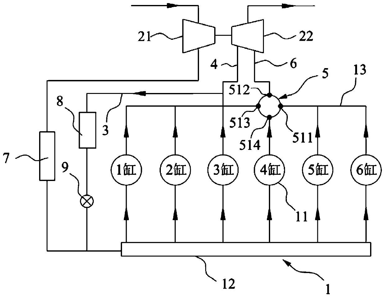
[0058] This embodiment provides an EGR system, such as Figure 2-5 As shown, it includes an engine 1 , a compressor 21 , a turbine 22 , an EGR pipeline 3 , an intercooler 7 , an EGR cooler 8 , an EGR valve 9 and a control valve 5 .

[0059] The engine 1 comprises at least two cylinders 11 and an intake manifold 12 and an exhaust manifold 13 communicating with each cylinder 11 respectively, such as figure 2 As shown, the engine 1 in this embodiment includes six cylinders 11 .

[0060] The input end of the compressor 21 communicates with the atmosphere, and the output end communicates with the main pipeline of the intake manifold 12; The second pipeline 6 communicates with the exhaust manifold 13, and the intercooler 7 is installed on the connecting pipeline between the compressor 21 and the main p...


PUM


Abstract

The invention relates to the field of engine EGR and particularly discloses an EGR system and a control method of the EGR system. The system comprises an engine, a gas compressor, a turbine motor, a control valve and an EGR pipeline. All cylinders of the engine communicate with an intake manifold and an exhaust manifold. The input end of the gas compressor communicates with the atmosphere, and theoutput end of the gas compressor communicates with the intake manifold. The turbine motor is connected with the gas compressor. The output end of the turbine motor communicates with the atmosphere, and the input end of the turbine motor is connected with the exhaust manifold through a first pipeline. One end of the EGR pipeline communicates with the first pipeline, and the other end of the EGR pipeline communicates with the intake manifold. The control valve is mounted on a main pipeline of the exhaust manifold. The control valve can be used for controlling the amount of part of waste gas which is exhausted from the cylinders and enters the first pipeline. According to the EGR system and the control method, the amount of the waste gas entering the first pipeline is controlled through thecontrol valve, and the problems that it is difficult to increase the EGR rate of the EGR system and the increase degree depends on the performance of a supercharger in the prior art are solved.

Description

technical field [0001] The invention relates to the field of engine EGR, in particular to an EGR system and a control method thereof. Background technique [0002] Exhaust Gas Recirculation (EGR) is to draw part of the exhaust gas generated by the diesel engine or gasoline engine out of the exhaust pipe, and introduce an appropriate amount of exhaust gas into the intake pipe through a control valve (such as the EGR valve) to mix with fresh air. It is an emission control technology that enters the combustion chamber to participate in combustion. Due to the large amount of CO contained in the exhaust gas 2 , while CO 2 It cannot burn but absorbs a large amount of heat, thereby reducing the combustion temperature of the mixture in the cylinder, thereby reducing NO X production volume. [0003] However, the upgrade of exhaust emission standards and the aging of the aftertreatment system make diesel engines need to increase the EGR rate. However, under the condition of a cert...

Claims


Application Information

Patent Timeline
Patent Type & Authority Patents(China)
IPC IPC(8): F02D21/08F02M26/04
CPCF02D21/08F02M26/04
Inventor 刘俊龙李卫李志杰
Owner WEICHAI POWER CO LTD
Learn More