Rotary fire grate of vertical pyrolysis gasification furnace

A technology of pyrolysis gasification and rotary grate, which is applied in the direction of rotary grate, incinerator, oscillating grate, etc. It can solve the problems of affecting the combustion-supporting air and garbage combustion-supporting effect, the grate is stuck, and the grate rotation resistance is large And other problems, to achieve the effect of full pyrolysis gasification incineration

Pending Publication Date: 2018-04-10
福建汇鑫环保科技股份有限公司
View PDF6 Cites 10 Cited by
  • Summary
  • Abstract
  • Description
  • Claims
  • Application Information

AI Technical Summary

Problems solved by technology

[0003] 1. In the process of high-temperature incineration of waste, it is easy to produce large pieces of coke. Only relying on the extrusion of the fire grate to break the slag, not only the effect of breaking the slag is not good, but also the large pieces of slag are easy to block the fire grate or get stuck on the slag discharge hole. The slag discharge is not smooth; and the grate rotation resistance is large, it is easy to cause the grate to get stuck and burn out the motor or reducer;
[0004] 2. After the combustion-supporting air enters through the ash bin, it will assist combustion from the slag discharge hole of the fire grate and the gap between the fire grates. If a large slagging hard object is blocked between the fire grates or stuck in the slag discharge hole, it will affect the combustion support Combustion-supporting effect of air and garbage;
[0005] 3. During the incineration process of the waste incinerator, the middle layer in the furnace is prone to the problem of fault arching

Method used


Image

  • Rotary fire grate of vertical pyrolysis gasification furnace
  • Rotary fire grate of vertical pyrolysis gasification furnace

Examples


Embodiment Construction

[0018] Embodiments of the present invention are described in detail below, examples of which are shown in the drawings, wherein the same or similar reference numerals designate the same or similar elements or elements having the same or similar functions throughout. The embodiments described below by referring to the figures are exemplary only for explaining the present invention and should not be construed as limiting the present invention.

[0019] In describing the present invention, it should be understood that the terms "center", "longitudinal", "transverse", "upper", "lower", "front", "rear", "left", "right", " The orientations or positional relationships indicated by "vertical", "horizontal", "top", "bottom", "inner" and "outer" are based on the orientations or positional relationships shown in the drawings, and are only for the convenience of describing the present invention and Simplified descriptions, rather than indicating or implying that the device or element refe...


PUM


Abstract

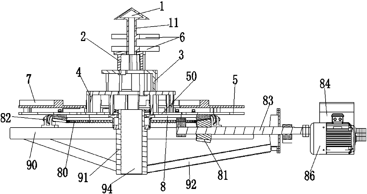
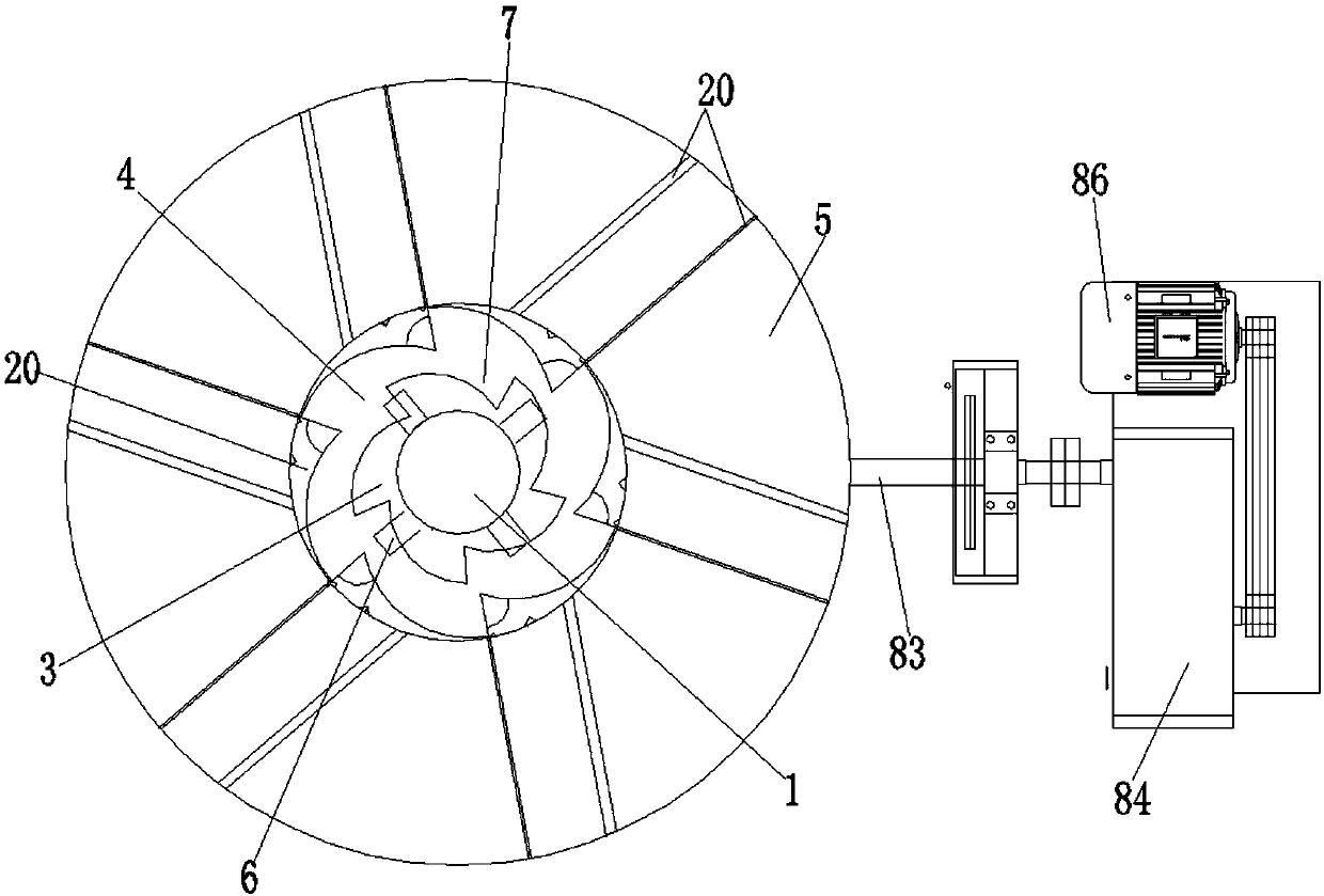
The invention discloses a rotary fire grate of a vertical pyrolysis gasification furnace. The rotary fire grate of the vertical pyrolysis gasification furnace comprises a cone cap, a small fire grate,a medium fire grate, a large fire grate and a fire grate plate connected in sequence from top to bottom, wherein the cone cap is axially provided with an integrally molded cone cap cylinder; at leasttwo layers of stirring shafts are arranged on the outer side of the cone cap cylinder; multiple scrapers are arranged on the upper surface of the fire grate plate in the peripheral direction; the fire grate plate is provided with a slag discharge hole; and a rotating plate is arranged on the lower surface of the fire grate plate, and is arranged on a fixed frame through a bearing. The rotary firegrate of the vertical pyrolysis gasification furnace further comprises a rotating mechanism for driving the rotating plate to rotate; the rotating mechanism comprises a gear row on the rotating plate, a gear, a support wheel and a transmission shaft; the gear row is driven to rotate by the gear on the transmission shaft to realize the process of a rotating mechanism easily driving the rotating plate to rotate; massive lagging hard matters of the rotary fire grate are repeatedly stirred, extruded and crushed; and combustion assisting air is fed from a gap between the slag discharge hole and the fire grate to fully mix with garbage materials so as to realize full pyrolysis, gasification and incineration of materials.

Description

technical field [0001] The invention relates to the technical field of solid waste treatment and incineration, in particular to a rotary grate of a vertical pyrolysis gasification furnace. Background technique [0002] The vertical pyrolysis gasification incinerator is a new type of waste disposal equipment. The rotary grate is the main component of the vertical pyrolysis gasification incinerator. The rotary grate mainly plays the following functions: one is the supporting function, holding up the waste materials The process of burning, pyrolyzing, gasifying, and drying garbage materials in the furnace; the second is the function of stirring and breaking slag, and the large slag produced after the complete combustion in the furnace is stirred and broken and then discharged; the third is slagging The function is to discharge the slag burned in the furnace and the broken residue out of the furnace body. The existing rotary grate has the following defects: [0003] 1. In the ...

Claims


Application Information

Patent Timeline
Patent Type & Authority Applications(China)
IPC IPC(8): F23G5/44F23H9/00
CPCF23G5/44F23H9/00F23H2700/005F23H2700/009
Inventor 吴晓龙
Owner 福建汇鑫环保科技股份有限公司
Why Eureka
Try Eureka