Fixture for testing superhigh-temperature tensile property of conductor material and clamping method

A technology of tensile properties and conductor materials, applied in the field of mechanical clamping, can solve the problems of low cooling efficiency of the fixture, unable to meet the requirements of material mechanical properties test, etc., and achieve the effect of good clamping effect, easy operation and convenient operation.

Inactive Publication Date: 2018-04-10
HARBIN INST OF TECH
View PDF9 Cites 8 Cited by
  • Summary
  • Abstract
  • Description
  • Claims
  • Application Information

AI Technical Summary

Problems solved by technology

[0005] The fixtures in the above inventions and documents are mainly aimed at tensile testing of metal materials in high-temperature environments, including plates and pipes, etc., and the temperature is mostly below 1000°C, and some fixtures have low cooling efficiency and cannot meet the ultra-high temperature (≥1800°C) environment. Material mechanical properties test requirements under

Method used


Image

  • Fixture for testing superhigh-temperature tensile property of conductor material and clamping method
  • Fixture for testing superhigh-temperature tensile property of conductor material and clamping method
  • Fixture for testing superhigh-temperature tensile property of conductor material and clamping method

Examples


specific Embodiment approach 1

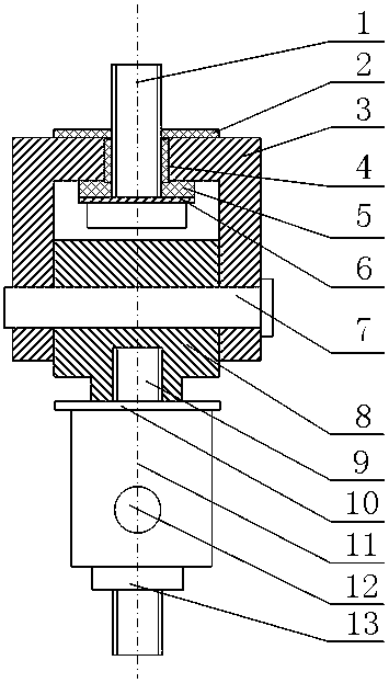
[0034] Specific implementation mode one: as Figure 1-Figure 7 As shown, this embodiment discloses a fixture for testing the ultra-high temperature tensile properties of conductor materials, including an upper water-cooled chuck, an upper tensile joint, a lower water-cooled chuck, and a lower connecting rod;

[0035]The upper water-cooled chuck and the lower water-cooled chuck have the same structure and size, and both include a water-cooled chuck body 14, four water-cooled pipes 15 and four arc-shaped pads 16; the upper tensile joint includes the first A screw 1, the first insulating pad 2, the first connector 3, the first insulating sleeve 4, the second insulating pad 5, the first washer 6, the first pin 7, the first connecting block 8, the second screw 9, the first Two washers 10, the second connecting head 11, the second pin 12 and the second connecting block 13; the lower connecting rod includes a shaft connecting sleeve 18, a second insulating sleeve 19, a third insulati...

specific Embodiment approach 2

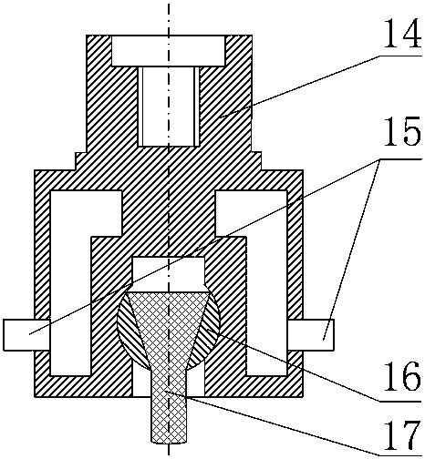
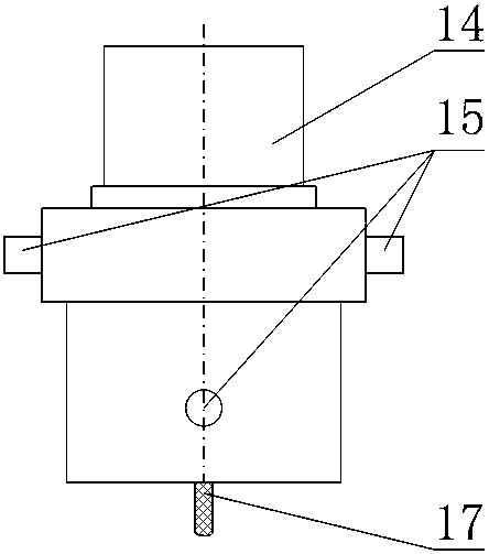
[0036] Specific implementation mode two: as image 3 As shown, this embodiment is a further description of Embodiment 1. The difference between every two adjacent water-cooled tubes 15 is 90°, and the two opposite water-cooled tubes 15 are on the same plane, and the two adjacent water-cooled tubes 15 are on different planes, the two water-cooling pipes 15 at the bottom are water inlet pipes, and the two water-cooling pipes 15 at the higher position are water outlet pipes. During the test, circulating cooling water was introduced into the water-cooling pipe 15 .

specific Embodiment approach 3

[0037] Specific implementation mode three: as Figure 4 , Figure 5 As shown, this embodiment is a further description of Embodiment 1. The lower connecting rod also includes four third screws 20; 20 connection, each third screw 20 is insulated from the shaft connection sleeve 18 and the metal positioning plate 22 through the third insulating sleeve 21 (between the upper end of each third insulating sleeve 21 and the head end of the third screw 20 and each A third washer 23 is respectively provided between the lower end of the third insulating sleeve 21 and the nut locked on the third screw 20).


PUM


Abstract

The invention discloses a fixture for testing the superhigh-temperature tensile property of a conductor material and a clamping method, and belongs to the technical field of mechanical clamping. A first bolt and a central hole of a first connecting head are insulated from each other, the head end of the first bolt and the first connecting head are insulated from each other, a first connecting block is arranged in the first connecting head, the first connecting block is connected with the first connecting head through a first pin, and the first connecting block is connected with a second connecting head; a second connecting block is arranged in the second connecting head, and the second connecting block is connected with the second connecting head through a second pin; an upper stretching connecting head is connected with an inner threaded hole of the water cooling clamp head body of an upper water cooling clamp head through a threaded column of the second connecting block; four water cooling pipes communicated with an annular sealed cavity of the water cooling clamp head body are fixed to the periphery of the water cooling clamp head body; a metal locating disc is arranged in a shaft connecting sleeve, detachably connected with the shaft connecting sleeve, insulated from the shaft connecting sleeve and connected with a lower water cooling clamp head. The fixture is used for testing the superhigh-temperature tensile property of the conductor material.

Description

technical field [0001] The invention relates to an ultra-high temperature stretching fixture and a clamping method, belonging to the technical field of mechanical clamping. Background technique [0002] With the development of aerospace technology, the requirements for the speed of aircraft are getting higher and higher, and hypersonic aircraft has become one of the trends in future development. During the flight of a hypersonic vehicle, the surface and the atmosphere produce severe friction, which generates severe aerodynamic heat. The thermal protection system becomes a key subsystem of the vehicle. Testing the mechanical properties of thermal protection materials in ultra-high temperature environments plays an important role in the design of thermal protection systems. [0003] At present, the heating methods for materials mainly include electric heating, radiation heating and induction heating. Electric heating has the advantages of fast heating rate, simple operation ...

Claims


Application Information

Patent Timeline
Patent Type & Authority Applications(China)
IPC IPC(8): G01N3/04
CPCG01N3/04G01N2203/0012G01N2203/0017G01N2203/0226G01N2203/04
Inventor 孟松鹤许承海韩新星金华易法军
Owner HARBIN INST OF TECH
Why Eureka
Try Eureka