Improved fluid iron removal method and device

A fluid and permanent magnet device technology, which is applied in the field of improved fluid iron removal methods and devices, can solve the problems of unsatisfactory iron removal effect and incomplete cleaning, and achieve the effects of easy operation, good effect and improved efficiency

Active Publication Date: 2018-04-13
江西铜业铅锌金属有限公司
View PDF7 Cites 0 Cited by
  • Summary
  • Abstract
  • Description
  • Claims
  • Application Information

AI Technical Summary

Problems solved by technology

[0002] The iron removal of the existing ceramic slurry is carried out by pouring the ceramic slurry into the channel filled with soft magnetic cut-off in the north-south magnetic field. For cleaning, it is generally introduced from top to bottom. Although there is less residual slurry during cleaning, it is easy to form solid-liquid-gas three-phase fluid that causes the flow rate to be too fast, and the slurry fluid that passes through the soft magnetic me

Method used


Image

  • Improved fluid iron removal method and device
  • Improved fluid iron removal method and device
  • Improved fluid iron removal method and device

Examples


Example Embodiment

[0024] The technical solutions in the embodiments of the present invention will be clearly and completely described below in conjunction with the accompanying drawings in the embodiments of the present invention. Obviously, the described embodiments are only a part of the embodiments of the present invention, rather than all the embodiments. Based on the embodiments of the present invention, all other embodiments obtained by those of ordinary skill in the art without creative work shall fall within the protection scope of the present invention.
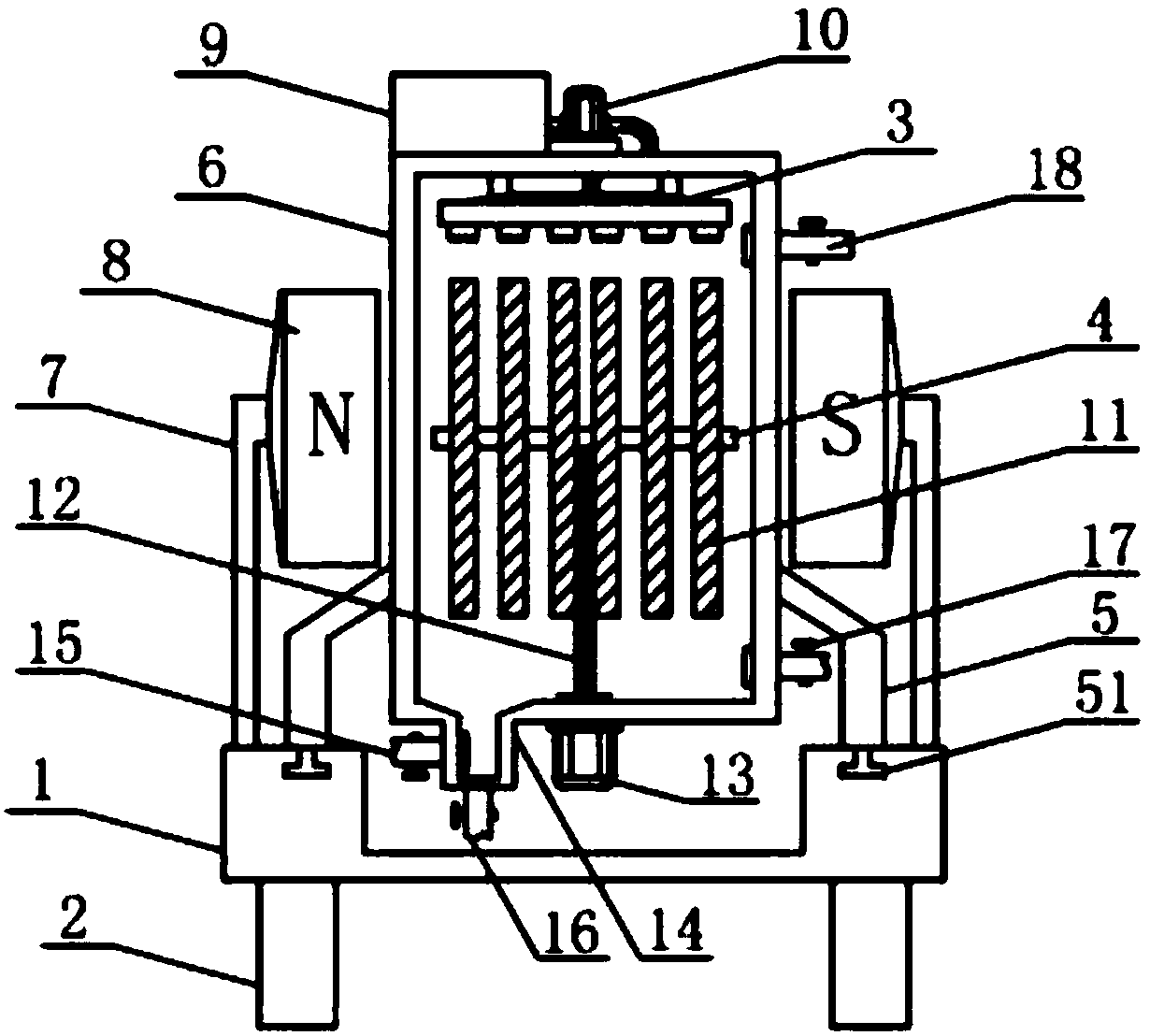
[0025] See Figure 1-3 , The present invention provides a technical solution: an improved fluid iron removing device, comprising a support base 1, a support 2 is installed at the bottom of the support base 1, and a mobile support 5 is installed symmetrically at the top of both sides of the support base 1, two groups of mobile The brackets 5 are respectively installed on the outer wall of the bottom of the fluid storage box 6, and the bot...


PUM


Abstract

The invention discloses an improved fluid iron removal device in the technical field of fluid iron removal. Two movable supports are installed on the outer walls of the bottom of a fluid storage box respectively, and a sliding strip is arranged at the bottom of each movable support; sliding grooves matched with the sliding strips are formed in the top of a supporting base, and supporting rods areinstalled on the two sides of the top of the supporting base; permanent magnet devices which correspond to each other are arranged at the opposite inner side ends of the two supporting rods, and the permanent magnet devices are arranged on the outer walls of the two sides of the fluid storage box respectively; the permanent magnet devices are not attached to the fluid storage box, the movable supports are arranged on the inner sides of the two supporting rods, a clear water tank is arranged on the left side of the top of the fluid storage tank, a water pipe is inserted into the outer wall of the right side of the clear water tank, and the other end of the water pipe is connected with a water inlet of a water pump. The device is convenient to operate, a liquid discharge pipe, a slag discharging pipe, a liquid inlet pipe and a liquid outlet pipe are controlled to be opened and closed through control valves, and the operations of iron removal, cleaning and slag removal are facilitated.

Description

technical field [0001] The invention relates to the technical field of fluid iron removal, in particular to an improved fluid iron removal method and device. Background technique [0002] The iron removal of the existing ceramic slurry is carried out by pouring the ceramic slurry into the channel filled with soft magnetic cut-off in the north-south magnetic field. For cleaning, it is generally introduced from top to bottom. Although there is less residual slurry during cleaning, it is easy to form solid-liquid-gas three-phase fluid that causes the flow rate to be too fast, and the slurry fluid that passes through the soft magnetic medium It is drained from the bottom of the channel, affected by gravity and fluid flow properties, the flow rate of the slurry fluid flowing through the soft magnetic medium is too fast, especially the flow rate of the slurry fluid in the middle is faster than that of the slurry fluid on both sides, thus As a result, the iron removal effect is no...

Claims


Application Information

Patent Timeline
IPC IPC(8): B03C1/02
CPCB03C1/02B03C2201/18
Inventor 倪以秀
Owner 江西铜业铅锌金属有限公司
Why Eureka
Try Eureka