Air cylinder sleeve clamp

A cylinder liner and fixture technology, which is applied in the field of cylinder liner fixtures, can solve problems such as poor positioning reliability, affecting machining accuracy, and surface quality problems, and achieve high positioning accuracy, good clamping reliability, and short time.

Active Publication Date: 2018-04-13
UNIV OF JINAN
View PDF12 Cites 7 Cited by
  • Summary
  • Abstract
  • Description
  • Claims
  • Application Information

AI Technical Summary

Problems solved by technology

[0003] Chinese patent document CN204565725U adopts the method of setting an expansion sleeve at both ends of the cylinder liner to position and clamp the cylinder liner, wherein the expansion sleeve has teeth, and there is a clamping stroke during clamping, and the teeth are pressed against the cylinder liner above, damage may form on the cylinder liner, causing surface quality problems
If there are few internal support points and the support area is small, the positioning reliability is relatively poor. For the use of flexible parts for support, the positioning position will change slightly due to the influence of cutting force, which will affect the overall processing accuracy.
[0005] Chinese patent document CN107243760A discloses a cylinder liner reaming fixture, which positions the two ends of the cylinder liner, the positioning parts are similar to the three-jaw chuck, and the claws of the three-jaw chuck have anti-slip teeth, as mentioned above , the existence of teeth will make the surface of the cylinder liner prone to surface quality problems. In addition, the three-jaw chuck structure is usually used for end clamping, which itself has a small contact area with the cylinder liner.
This kind of structure has the inherent defects of the cam structure, which belongs to the low-level mechanism, the transmission efficiency is low, and the force required for actual operation is relatively large.

Method used


Image

  • Air cylinder sleeve clamp
  • Air cylinder sleeve clamp
  • Air cylinder sleeve clamp

Examples


Embodiment Construction

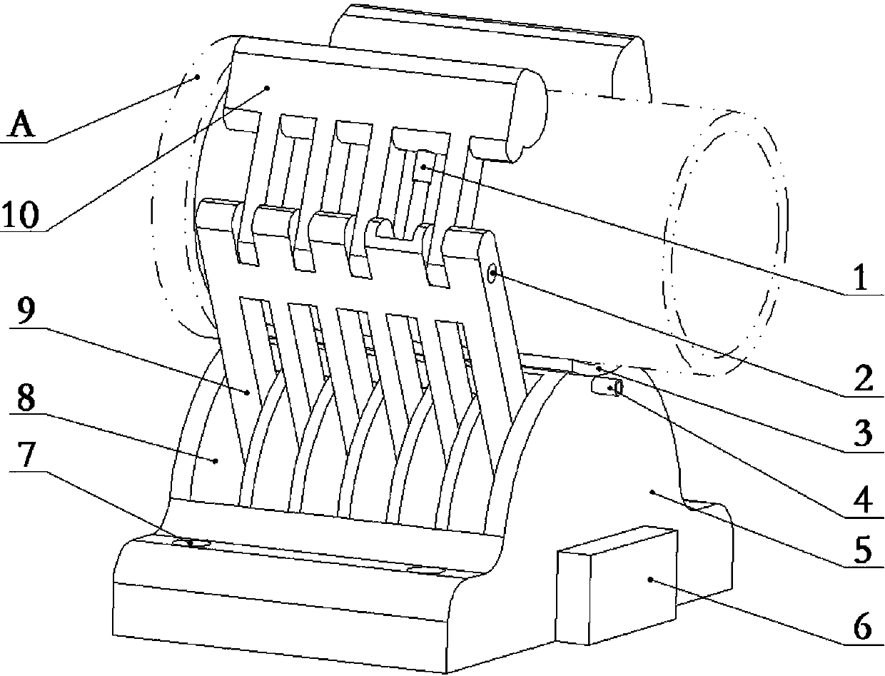
[0035] Refer to the attached figure 1 A cylinder liner clamp, in the figure, is a cylinder liner clamp in which the cylinder liner A to be positioned is clamped horizontally, but it can also be laid down to clamp the cylinder liner A in the vertical direction.

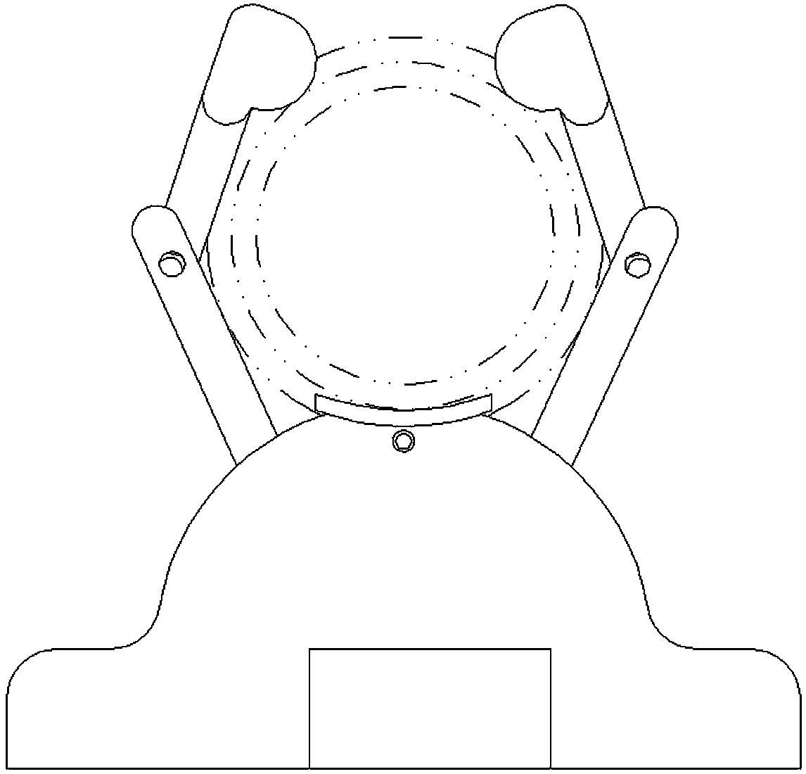
[0036] From figure 2 It can be seen from the figure that the cylinder liner fixture as a whole is a plane-symmetric structure, and the corresponding plane of symmetry is in figure 2 Middle is the vertical plane passing the axis of cylinder liner A.

[0037] Furthermore, in figure 1 Among them, the base 5 of the cylinder liner fixture is a plane-symmetrical structure about a given symmetrical plane. The symmetrical plane in the figure is a vertical plane. The top of the base 5 provides an initial support structure, so that the workpiece, that is, the cylinder Sleeve A is placed on the initial support structure before it is clamped.

[0038] Correspondingly, the initial support structure is also symmetrical about t...


PUM


Abstract

The invention discloses an air cylinder sleeve clamp which comprises a base, a first swing mechanism, a second swing mechanism and a synchronous driving device, wherein the base is a plane symmetry structure relative to a given symmetrical plane; the base provides an initial support structure; the initial support structure is also symmetrical relative to the given symmetrical plane; the first swing mechanism is mounted on one side of the symmetrical plane on the base and is provided with a first V-shaped positioning part; the corresponding first swing axis is parallel with the symmetrical plane and the positioned air cylinder sleeve; the first swing mechanism and the second swing mechanism are symmetrical relative to the symmetrical plane; the second swing mechanism is mounted on the baseand provides a second V-shaped positioning part; and the synchronous driving device is used for synchronously driving the first swing mechanism and the second swing mechanism to enable the two swingmechanisms to move in the same or opposite directions. The air cylinder sleeve clamp can clamp the air cylinder sleeve in a fast and reliable manner.

Description

technical field [0001] The invention relates to a cylinder liner clamp. Background technique [0002] The cylinder liner is an important part of the engine, and its performance directly affects the overall performance of the engine, and even affects the performance of the machine. Therefore, the manufacture of cylinder liners is very important. [0003] Chinese patent document CN204565725U adopts the method of setting an expansion sleeve at both ends of the cylinder liner to position and clamp the cylinder liner, wherein the expansion sleeve has teeth, and there is a clamping stroke during clamping, and the teeth are pressed against the cylinder liner On the other hand, damage may form on the cylinder liner, causing surface quality problems. [0004] Chinese patent document CN106041794A discloses a clamp for cylinder liner clamping based on bulging, which includes a mounting plate and a clamping mandrel vertically installed under the mounting plate. The segments are conne...

Claims


Application Information

Patent Timeline
Patent Type & Authority Applications(China)
IPC IPC(8): B23Q3/06B25B11/00
CPCB23Q3/062B25B11/00Y02E60/32
Inventor 薛传艺王守仁温道胜王高琦王立虎颜新宇付坤张晓东
Owner UNIV OF JINAN
Why Eureka
Try Eureka