Mechanical arm for automatically mounting and demounting hub

A technology of mechanical arms and hubs, applied in the field of mechanical arms for automatic loading and unloading of hubs, can solve the problems of low work efficiency, high cost, time-consuming and laborious, etc., and achieve the effect of being suitable for application and promotion with remarkable effects

Pending Publication Date: 2018-04-13
BINZHOU UNIV
View PDF9 Cites 4 Cited by
  • Summary
  • Abstract
  • Description
  • Claims
  • Application Information

AI Technical Summary

Problems solved by technology

This method of using manpower to carry the wheel hub is not only time-consuming and laborious, but also relatively low work efficiency
[0003] If the existing articulated manipulator is used to transport the wheel hub, the cost of a 60kg articulated manipulator is generally more than 300,000 yuan. If a set of wheels worth more than 300,000 yuan is purchased just for the purpose of transporting the wheel hub, for ordinary enterprises Undoubtedly, the cost is too high, so it is necessary to design a low-cost mechanical device that can complete the loading and unloading of the wheel hub

Method used


Image

  • Mechanical arm for automatically mounting and demounting hub
  • Mechanical arm for automatically mounting and demounting hub
  • Mechanical arm for automatically mounting and demounting hub

Examples


Embodiment Construction

[0021] The present invention will be further described below in conjunction with the accompanying drawings and embodiments.

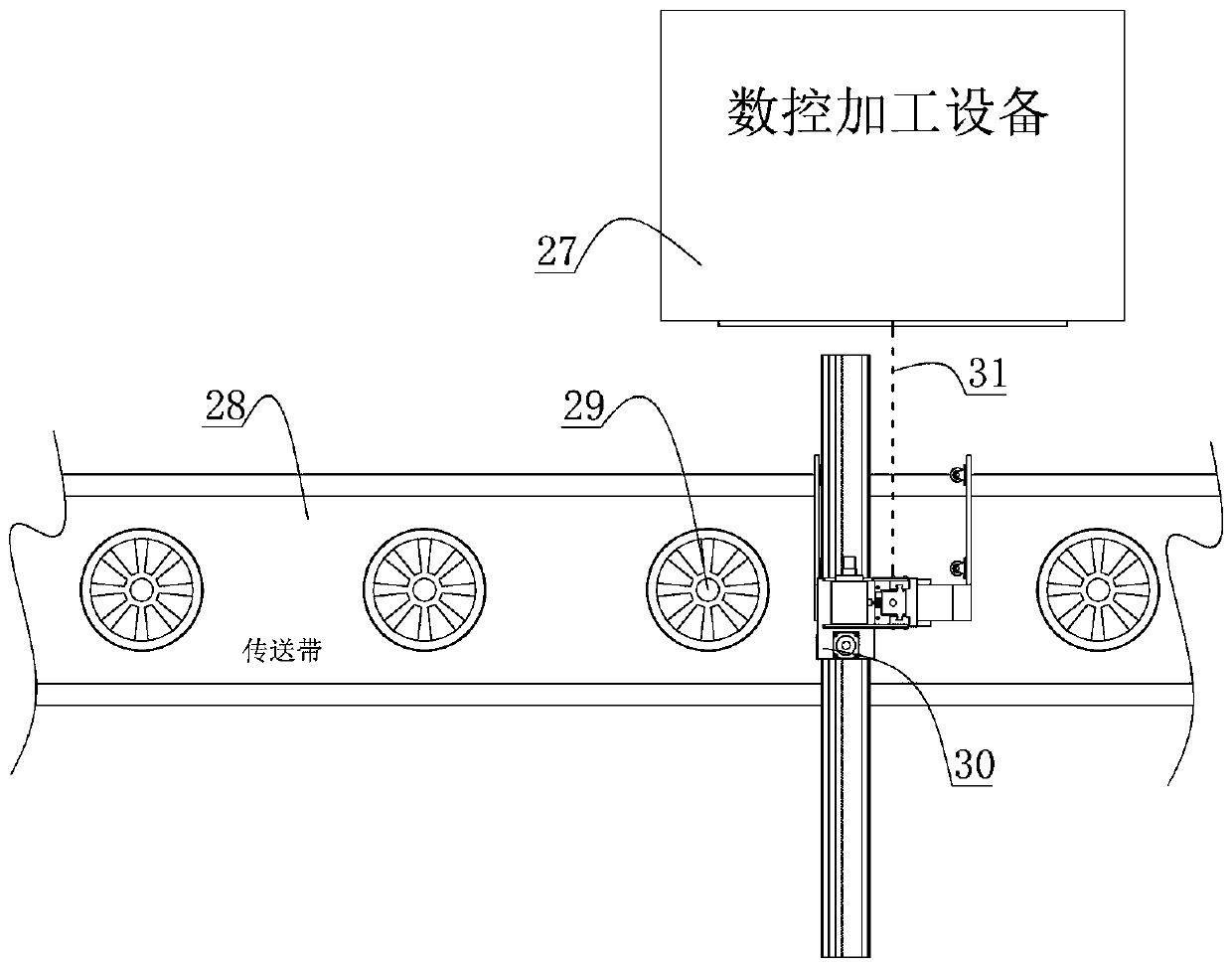
[0022] Such as figure 1 As shown, a schematic diagram of the use place of the mechanical arm for automatically loading and unloading the wheel hub of the present invention is given. Before the mechanical arm of the present invention is installed, the wheel hub 29 transported by the conveyor belt 28 needs to be manually transported to the numerical control processing equipment 27 After the CNC processing equipment 27 finishes processing the wheel hub 29, the worker will remove the wheel hub 29 from the clamping tool and place it on the conveyor belt 28; then move the next wheel hub 29 to be processed, and so on. cycle. It is undoubtedly time-consuming and labor-intensive to rely on manual handling of the wheel hub 29, and the labor cost is relatively high.

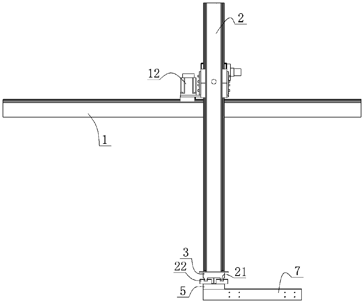
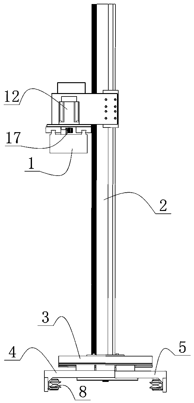
[0023] Such as Figure 2 to Figure 6 As shown, the front view, left view, right view, top view...


PUM


Abstract

The invention discloses a mechanical arm for automatically mounting and demounting a hub. The mechanical arm comprises a cross beam, a vertical beam, a bottom plate, a left sliding plate, a right sliding plate and an air cylinder. A base is arranged on the cross beam. The mechanical arm is characterized in that two lower guide rails are arranged on the bottom plate, and lower sliding blocks matched with the lower guide rails are fixed to the left sliding plate and the right sliding plate; a left clamping arm is fixed to the outer end of the left sliding plate, a right clamping arm is fixed tothe outer end of the right sliding plate, and clamping wheels are fixed to the inner side of the left clamping arm and the inner side of the right clamping arm; a first gear rack is fixed to the lowersurface of the left sliding plate, and a second gear rack is fixed to the lower surface of the right sliding plate; and a synchromesh gear engaged with the first gear rack and the second gear rack isarranged between the first gear rack and the second gear rack, a cylinder body of the air cylinder is fixed to the right sliding plate, and a piston rod of the air cylinder is fixed to the left sliding plate. According to the mechanical arm, it can be guaranteed that the left sliding plate and the right sliding plate do equidistant synchronous movement, and it is guaranteed that the clamped hub does not deflect; and the hub can be accurately conveyed to a clamping tool of numerical control machining equipment conveniently, the hub can be taken down from the clamping tool conveniently, and remarkable beneficial effects are achieved.

Description

technical field [0001] The invention relates to a mechanical arm for automatically loading and unloading a wheel hub, more specifically, to a mechanical arm for automatically loading and unloading a wheel hub that can automatically realize the centering of a clamped workpiece. Background technique [0002] With the continuous rise of labor costs and the development of mechanical automation, more and more links in the production process are continuously replaced by automated machinery. In the manufacturing industry, the loading and disassembly of workpieces to be processed is usually completed by manpower. Human handling is not only inefficient, but also requires multiple people to complete heavy workpieces, which is not conducive to saving labor costs. For example, during the processing of automobile wheels, workers need to remove the wheels on the conveyor belt and transport them to the holding tooling of the CNC processing equipment. After processing, the workers will remo...

Claims


Application Information

Patent Timeline
IPC IPC(8): B23Q7/14
CPCB23Q7/1405
Inventor 黄超
Owner BINZHOU UNIV
Why Eureka
Try Eureka