Supercharge Your Innovation With Domain-Expert AI Agents!

Check ring mechanism of injection molding machine

A non-return ring and injection molding machine technology, which is applied in the field of injection molding machines, can solve the problems of poor real-time heat transfer, increased power consumption, and blocked activities, and achieve the effects of reducing power consumption, increasing circulation resistance, and achieving stable sliding fit

Pending Publication Date: 2018-04-13
进顺汽车零部件如皋有限公司
View PDF0 Cites 2 Cited by
  • Summary
  • Abstract
  • Description
  • Claims
  • Application Information

AI Technical Summary

Problems solved by technology

[0002] The check valve is equivalent to the one-way valve inside the barrel. It is connected during the plasticization period. After the plastic particles are plasticized, they enter the front space of the barrel through the check valve, and then push the screw to inject. The front and rear parts of the barrel are isolated to prevent pressure release when injecting into the mold cavity, thereby ensuring the smooth progress of the injection process; the existing non-return ring slides on the inner wall of the barrel through the outer periphery, and uses its inner hole to form a channel. This structure When the plastic passes through the check valve, the heat generated by the heater outside the barrel needs to pass through the fit gap between the check ring and the barrel and then pass through the check ring to transfer to the plastic, making the real-time performance of heat transfer poor. , and the movement between the non-return ring and the barrel is easily blocked due to the difference in deformation between the two parties, which increases power consumption and causes wear

Method used


Image

  • Check ring mechanism of injection molding machine
  • Check ring mechanism of injection molding machine

Examples


Embodiment Construction

[0016] The present invention will be further described below with reference to the drawings and embodiments of the specification:

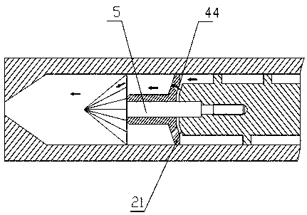
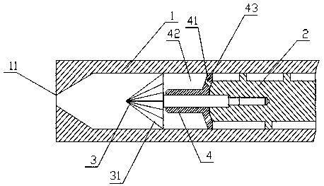
[0017] Such as figure 1 , figure 2 The shown non-return ring mechanism of the injection molding machine includes a barrel 1, a screw 2, a screw head 3, and a non-return ring 4. One end of the barrel is opened to form an injection port 11, the screw is placed in the barrel, and the screw head passes through a connecting rod. 5 It is fixedly connected to the end of the screw near the injection port, and the connecting rod is coaxial with the screw head and the screw; the diameter of the connecting rod is smaller than the diameter of the screw and the diameter of the end face of the screw head and the connecting rod, so that the connecting rod and the screw head, screw A step surface is formed between them; the non-return ring is straight cylindrical and can be axially movably sleeved on the connecting rod, and the one end surface of the non-return rin...


PUM


Abstract

The invention relates to a check ring mechanism of an injection molding machine. The check ring mechanism comprises a machine cylinder, a screw rod, a screw rod head and a check ring. The screw rod isarranged in the machine cylinder. The screw rod head is fixedly connected to the end, close to an injection opening, of the screw rod through a connecting rod, and the connecting rod is coaxial withthe screw rod head and the screw rod. The diameter of the connecting rod is smaller than the diameter of the screw rod and the diameter of the end face, connected with the connecting rod, of the screwrod head. The check ring is in a straight cylinder shape and can be axially and movably arranged on the connecting rod in a sleeving and hooping manner, in addition, the edge of the end face, close to the screw rod, of the check ring is spread and extends in the radial direction to form a round ring end face plate, and the edge of the ring end face plate makes contact with the inner wall of the machine cylinder in a sliding manner. Multiple through holes are formed in the ring end face plate. Outer circumference guiding of sliding of the check ring is changed into inner circumference guiding,the distance between the inner circumference of the check ring and a heater at the outer portion of the machine cylinder and the distance between the connecting rod and the heater at the outer potionof the machine cylinder are large, no large temperature difference exists between the check ring and the connecting rod, and therefore the check ring and the connecting rod can be matched stably, andthe phenomena that sliding is obstructed or even abrasion happens due to deformation differences are avoided.

Description

Technical field [0001] The invention relates to the field of injection molding machines, in particular to a non-return ring mechanism of an injection molding machine. Background technique [0002] The check valve is equivalent to the one-way valve inside the barrel. It conducts during plasticization. After plasticizing, the plastic particles enter the front space of the barrel through the check valve, and then push the screw for injection, the check valve will stop the machine. The front of the barrel is isolated from the rear to prevent the pressure from being released into the mold cavity, thereby ensuring the smooth progress of the injection process; the existing non-return ring slides on the inner wall of the barrel through the outer periphery, and uses its inner hole to form a channel. This structure When the plastic passes through the check valve, the heat generated by the heater outside the barrel needs to be transferred to the plastic through the matching gap between the ...

Claims


Application Information

Patent Timeline
IPC IPC(8): B29C45/50B29C45/60B29C45/58
CPCB29C45/50B29C45/58B29C45/60
Inventor 杨涛高绪为许波伟
Owner 进顺汽车零部件如皋有限公司
Features
  • R&D
  • Intellectual Property
  • Life Sciences
  • Materials
  • Tech Scout
  • Unparalleled Data Quality
  • Higher Quality Content
  • 60% Fewer Hallucinations
Learn More