Vibration wave roll and microsphere loading device for reflecting material
A vibratory wave and microbead technology, which is applied in lamination devices, chemical instruments and methods, lamination auxiliary operations, etc., can solve the problem of weak adhesion of the glue surface, excessive amount of reflective microbeads, scratches or tears of the substrate And other problems, to achieve the effect of improving viscosity, short duration and strong strength
- Summary
- Abstract
- Description
- Claims
- Application Information
AI Technical Summary
Problems solved by technology
Method used
Image

Examples
Embodiment 1
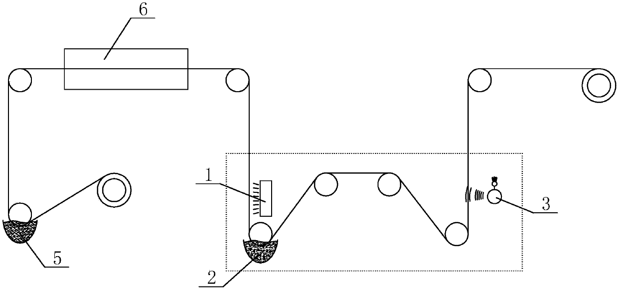
[0033] Such as figure 1 A microbead feeding device for reflective materials is shown, including a base material, a conveying roller for transporting the base material, a heating device 1, a bead holding hopper 2 and a removal mechanism for shaking off excess microbeads, The removal mechanism includes a longitudinal movement structure and a vibrating roller for maintaining the vertical movement of the substrate;
[0034] The heating device 1 is used to irradiate and heat the glue on the surface of the substrate; the surface of the substrate with the glue faces the heating device 1, and the heating device 1 is located in front of the bead hopper 2; the substrate heated by the heating device 1 rapidly Enter into the micro-bead hopper 2, the micro-bead hopper 2 is filled with a large amount of reflective micro-beads, after the surface of the substrate is heated, the glue adheres to a large number of reflective micro-beads; At the wave sending end, the vertical movement structure ...
Embodiment 2
[0040] This embodiment is based on Embodiment 1, which is optimized.
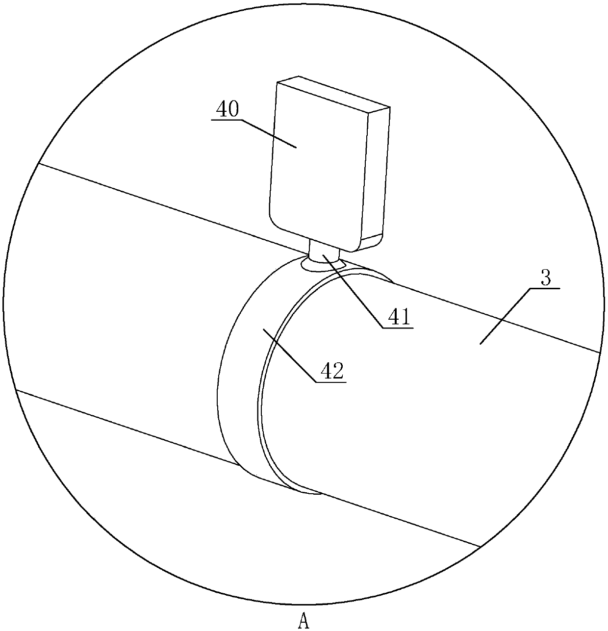
[0041] Such as Figure 6 and Figure 7 As shown, in Embodiment 2, the middle part of the vibrating part 40 is recessed to form a recess, and the recess direction of the recess is opposite to the rotation direction of the roller body 3 . The outer end of the vibrating part 40 is arc-shaped, and the arc-shaped opening at the outer end of the vibrating part 40 communicates with the concave part.
[0042] Through the concave part of the vibration part 40 and the arc-shaped opening at the outer end of the vibration part 40, the airflow is concentrated in the concave part where there is an arc-shaped opening to extrude the airflow, so that the airflow is more concentrated, and the impact points on the substrate are more concentrated to avoid The air flow is dispersed.
[0043] Such as Figure 7As shown, the vibrating part 40 is provided with a fixing hole 402, and the vibrating part 40 is provided with a coun...
Embodiment 3
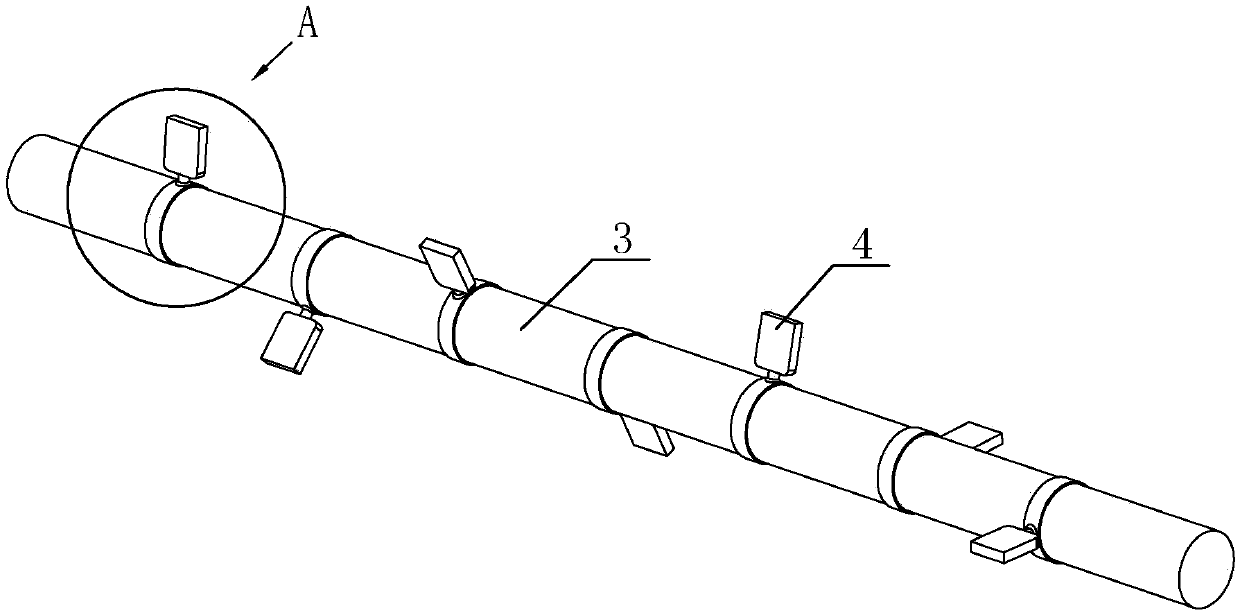
[0051] Such as Figure 4 As shown, the vibration wave device 4 is a fiber cloth bundled on the surface of the roller body 3, and the vibration wave part 40 is the extra cloth after bundling.
[0052] The vibrating part 40 in this embodiment is extra fiber cloth, even on the basis of the vibrating part 40, cloth pieces can be bundled to increase the weight of the vibrating part 40 and improve the airflow impact of the vibrating part 40.
PUM
 Abstract
Description
Claims
Application Information
 - Generate Ideas
- Intellectual Property
- Life Sciences
- Materials
- Tech Scout
- Unparalleled Data Quality
- Higher Quality Content
- 60% Fewer Hallucinations
Browse by: Latest US Patents, China's latest patents, Technical Efficacy Thesaurus, Application Domain, Technology Topic, Popular Technical Reports.
© 2025 PatSnap. All rights reserved.Legal|Privacy policy|Modern Slavery Act Transparency Statement|Sitemap|About US| Contact US: help@patsnap.com