
Concrete pouring formwork and construction method thereof

A construction method and concrete technology, applied in construction, artificial islands, water conservancy projects, etc., can solve the problems of difficulty in controlling the flatness of the integral formwork of the formwork, narrow operating space, cluttered construction site, etc., and it is easy to achieve flatness and appearance size. Control and operation space is spacious, and the effect of eliminating potential safety hazards

Inactive Publication Date: 2018-04-13
SUBWAY ENG CO LTD OF CHINA RAILWAY 16TH CONSTR BUREAU +2
View PDF4 Cites 2 Cited by
  • Summary
  • Abstract
  • Description
  • Claims
  • Application Information

AI Technical Summary

Problems solved by technology

[0004] 1. Slow formwork: Every time a cycle of concrete is poured, it is necessary to disassemble the shelf pipes, steel arches, and steel formwork, and then need to be erected again; and the operating space is narrow, and the integrity of the formwork and the flatness of the formwork are difficult to control. Time-consuming
[0005] 2. Slow demoulding: After removing the steel arch, remove the steel formwork piece by piece. Since the steel formwork is bonded together in the concrete arch ring, if one piece is removed, the other steel formwork may fall into pieces or fall completely. fall, resulting in severe deformation of the steel formwork, which poses a serious safety hazard
[0006] 3. Not environmentally friendly: The dismantled shelf tubes, steel arches, steel formwork and other spare parts are large in size and miscellaneous in variety, requiring a lot of labor to clean, sort, and stack, and occupying limited operating space. The construction site is very messy

Method used


Image

  • Concrete pouring formwork and construction method thereof
  • Concrete pouring formwork and construction method thereof
  • Concrete pouring formwork and construction method thereof

Examples


Embodiment Construction

[0033] The following will clearly and completely describe the technical solutions in the embodiments of the present invention with reference to the accompanying drawings in the embodiments of the present invention. Obviously, the described embodiments are only some, not all, embodiments of the present invention. All other embodiments obtained by persons of ordinary skill in the art based on the embodiments of the present invention belong to the protection scope of the present invention.

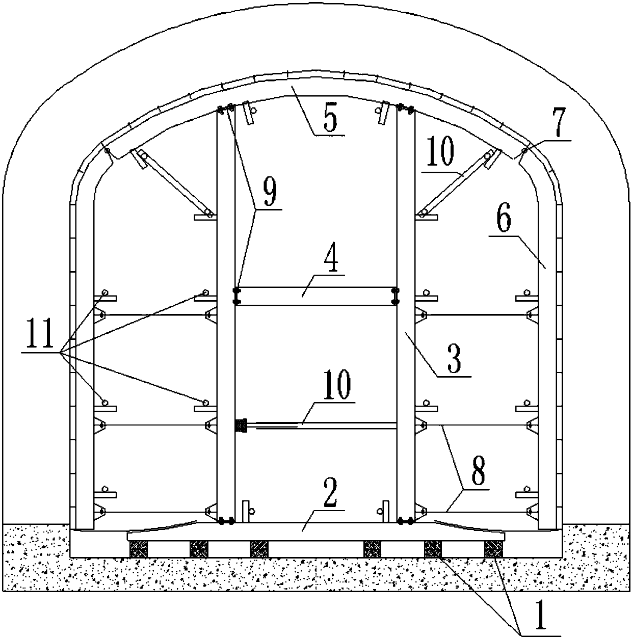
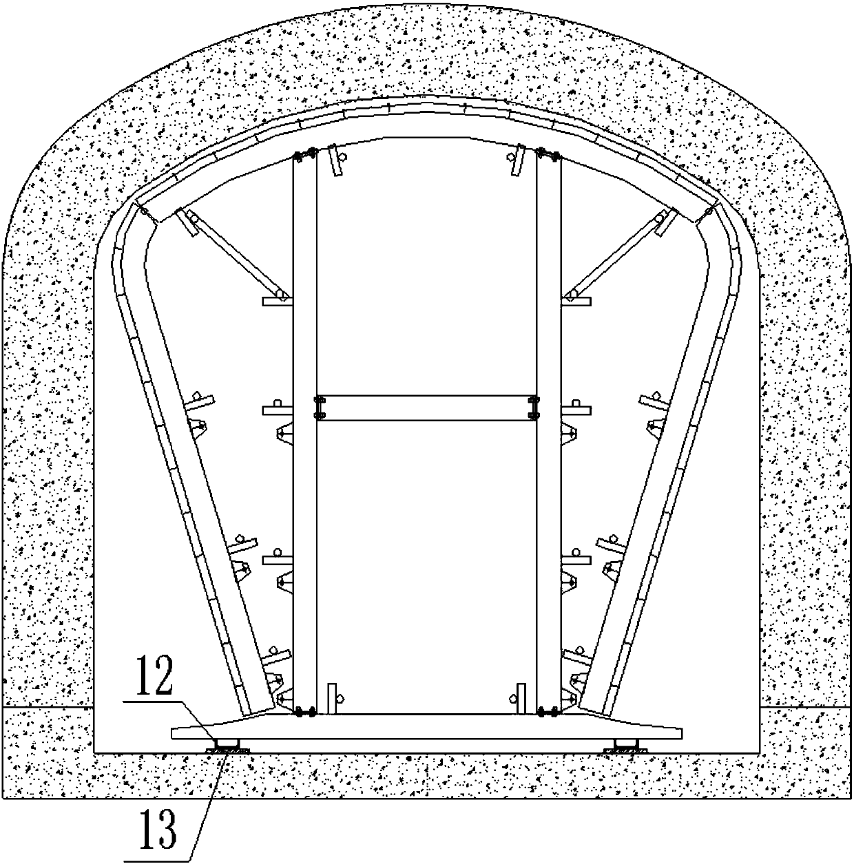
[0034] Such as figure 1 and figure 2 As shown, a concrete pouring formwork according to the embodiment of the present invention includes several formwork main bodies connected in sequence, the formwork main body includes a liftable and movable base 2, and the base 2 passes through several columns 3 The top arch 5 positioned above the base 2 is fixedly connected, and side wall arches 6 are respectively hinged on both sides of the top arch 5, and several The top wire 8 is detachable, and sev...


PUM


Abstract

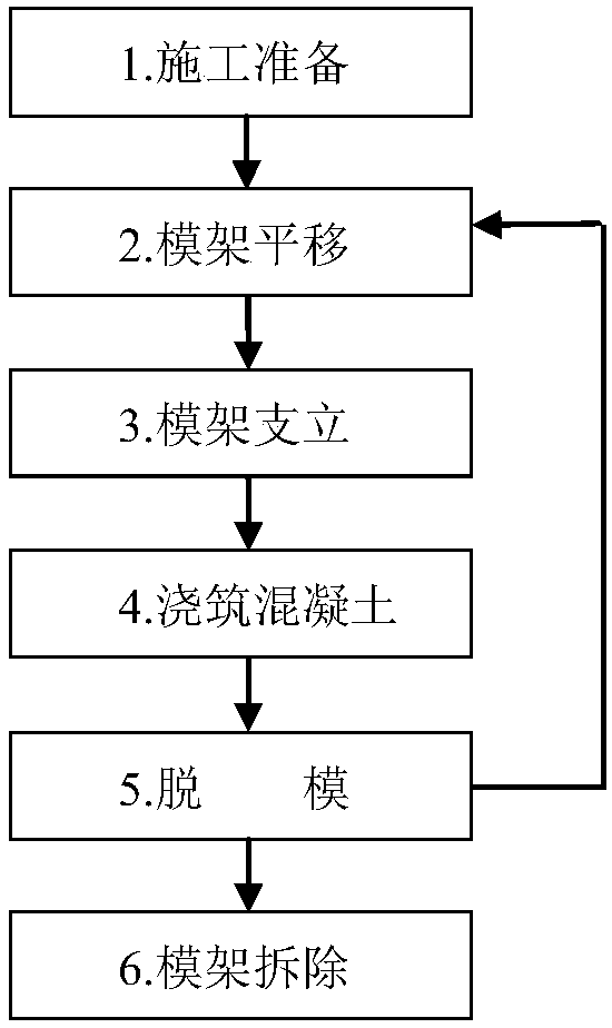
The invention discloses a concrete pouring formwork and a construction method thereof. The concrete pouring formwork comprises a plurality of formwork main bodies which are sequentially connected; theformwork main bodies comprise bases which can be lifted and moved; the bases are fixedly connected with top arching frames located above the corresponding bases through a plurality of upright columns; the two sides of the top arching frames are hinged with side wall arching frames correspondingly; a plurality of detachable jack screws are connected between each side wall arching frame and the upright column closest to the corresponding side wall arching frame; and a plurality of steel templates are spread on the top arching frames and the side wall arching frames. Frame erecting is rapid, nofrequent disassembly or assembly is required, overall movement and moving in place can be carried out, the concrete surface evenness and the appearance size are easy to control, and the labor and timeare saved. Demoulding is rapid, and the demoulding can be completed simply by disassembling the jack screws and lowering the height of the concrete pouring formwork. Environment protection is facilitated, by adopting the construction method, the frame erecting and the demoulding can be carried out without frequently disassembling the concrete pouring formwork or the steel templates, sundries on aconstruction site are few, an operating space is wide, a rod is clear, and civilization construction is facilitated.

Description

technical field [0001] The invention relates to the technical field of concrete pouring formwork, in particular to a concrete pouring formwork and a construction method thereof. Background technique [0002] In the construction of underground engineering, due to the limitation of the site, structure and other environment and use functions, its cross-section forms are becoming more and more diverse, especially the locations of auxiliary works such as cross passages, entrances and exits are scattered and messy, and the cross-section changes frequently and multi-terminal; this gives The construction of molded concrete has added a lot of difficulty. The lining trolley is bulky and expensive, and cannot be turned in curved sections and cannot stand in sloped sections. Can't even think about it. [0003] The traditional method is to use shelf tubes, steel arches, steel formwork, and artificial formwork. Traditional methods have the following shortcomings: [0004] 1. Slow form...

Claims


Application Information

Patent Timeline
Patent Type & Authority Applications(China)
IPC IPC(8): E02D29/045
CPCE02D29/045
Inventor 戴兴民董贤顺曹德更张朋戴兵董君米献芳
Owner SUBWAY ENG CO LTD OF CHINA RAILWAY 16TH CONSTR BUREAU
Learn More