Temperature control system for bearing block of compressor

A temperature control system, compressor bearing technology, used in mechanical equipment, machines/engines, liquid fuel engines, etc., can solve problems such as poor lubrication, poor oil film cooling, and bearing stuck

Inactive Publication Date: 2018-04-13
ANHUI BOGUTE ELECTRICAL & MECHANICAL TECH CO LTD
View PDF10 Cites 0 Cited by
  • Summary
  • Abstract
  • Description
  • Claims
  • Application Information

AI Technical Summary

Problems solved by technology

[0003] At present, the movable scroll drive bearings of scroll compressors at home and abroad do not have a special lubricating and cooling structure, but only use the mixture of refrigerant steam and lubricating oil to blow, cool and lubricate the side of the drive bearing, resulting in insufficient lubricating oil and steam reaching The surface of the ball makes it impossible to form a sufficient thickness of oil film on the surface of the ball and the cooling is poor, and it is in a state of poor lubrication. With the increase of the running time of the product, the friction temperature between the ball and the raceway will increase, the wear will increase, and the bearing will occur in severe cases. stuck fault

Method used


Image

  • Temperature control system for bearing block of compressor
  • Temperature control system for bearing block of compressor

Examples


Embodiment 1

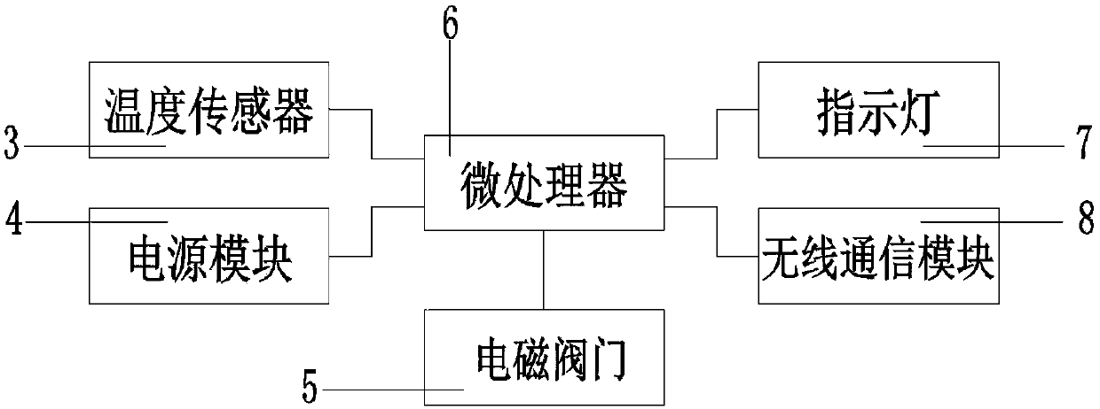
[0019] like figure 1 As shown, a compressor bearing seat temperature control system includes a microprocessor 6, a temperature sensor 3 and a power module 4, the temperature sensor 3 and the power module 4 are connected to the microprocessor 6, and the microprocessor 6 Connect to the electromagnetic valve 5, the indicator light 7 and the wireless communication module 8.

[0020] Preferably, the temperature sensor 3 , the power module 4 , the microprocessor 6 and the wireless communication module 8 are all installed inside the first cavity 9 .

[0021] Preferably, the temperature sensor 3 is DS18B20.

[0022] Preferably, the indicator light 7 is an LED light.

[0023] Preferably, the wireless communication module 8 is a Bluetooth communication module.

Embodiment 2

[0025] A compressor bearing seat temperature control system, including a microprocessor 6, a temperature sensor 3 and a power module 4, the temperature sensor 3 and the power module 4 are connected to the microprocessor 6, and the microprocessor 6 is connected to the electromagnetic On the valve 5, the indicator light 7 and the wireless communication module 8.

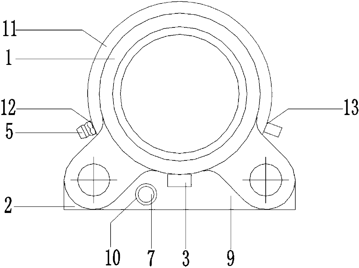
[0026] like figure 2 As shown, preferably, the temperature sensor 3 is installed in the base 2 close to the bearing outer ring 1, the base 2 also has a hole 10, and the indicator light 7 is embedded in the hole 10; the bearing outer The ring 1 is also provided with a second cavity 11, the second cavity 11 is provided with an oil outlet 12 and an oil inlet 13, and the oil inlet 13 is connected to the oil tank through the electromagnetic valve 5.

[0027] Preferably, the temperature sensor 3 , the power module 4 , the microprocessor 6 and the wireless communication module 8 are all installed inside the first cavity 9 ....

Embodiment 3

[0032] A compressor bearing seat temperature control system, including a microprocessor 6, a temperature sensor 3 and a power module 4, the temperature sensor 3 and the power module 4 are connected to the microprocessor 6, and the microprocessor 6 is connected to the electromagnetic On the valve 5, the indicator light 7 and the wireless communication module 8.

[0033] Preferably, the temperature sensor 3 is installed in the base 2 close to the bearing outer ring 1, the base 2 is also provided with a hole 10, and the indicator light 7 is embedded in the hole 10; the bearing outer ring 1 is also A second cavity 11 is provided, and the second cavity 11 is provided with an oil outlet 12 and an oil inlet 13, and the oil inlet 13 is connected to the oil tank through the electromagnetic valve 5.

[0034] Preferably, the temperature sensor 3 , the power module 4 , the microprocessor 6 and the wireless communication module 8 are all installed inside the first cavity 9 .

[0035] Pref...


PUM


Abstract

The invention provides a temperature control system for a bearing block of a compressor and relates to an online monitoring system for bearings. The temperature control system comprises a microprocessor, a temperature sensor and a power module; the temperature sensor and the power module are connected with the microprocessor; and the microprocessor is connected with an electromagnetic valve, an indicating lamp and a wireless communication module. The temperature control system for the bearing block of the compressor is simple in structure, convenient to mount and relatively low in cost, oil cooling can be performed on a bearing automatically while detection is performed, and on-site processing by an operating person is facilitated.

Description

technical field [0001] The invention relates to the field of bearings, in particular to a temperature control system for a bearing seat of a compressor. Background technique [0002] The main function of the movable scroll drive bearing is to realize the rotation of the movable scroll under the drive of the motor, and realize the compression of the gas together with the fixed scroll. [0003] At present, the movable scroll drive bearings of scroll compressors at home and abroad do not have a special lubricating and cooling structure, but only use the mixture of refrigerant steam and lubricating oil to blow, cool and lubricate the side of the drive bearing, resulting in insufficient lubricating oil and steam reaching The surface of the ball makes it impossible to form a sufficient thickness of oil film on the surface of the ball and the cooling is poor, and it is in a state of poor lubrication. With the increase of the running time of the product, the friction temperature bet...

Claims


Application Information

Patent Timeline
IPC IPC(8): F04C28/00F04C28/28F04C29/02F04C29/04C10M169/04C10N30/04C10N30/06C10N40/02
CPCC10M169/045C10M2201/041C10M2201/062C10M2203/1065C10M2207/026C10M2207/401C10M2215/223C10M2223/041C10N2030/04C10N2030/06C10N2040/02F04C28/00F04C28/28F04C29/021F04C29/042F04C2240/56F04C2240/81
Inventor 刘朝能黄先州葛勤贵袁正发宛新芬
Owner ANHUI BOGUTE ELECTRICAL & MECHANICAL TECH CO LTD
Why Eureka
Try Eureka