
High-power transmitter cooling apparatus

A high-power transmitter and cooling device technology, applied in the direction of cooling/ventilation/heating transformation, electrical components, electrical equipment structural parts, etc., can solve problems affecting the working efficiency of the transmitter, transmitter damage, etc., to achieve simple structure, Guaranteed efficiency and reliability, and the effect of meeting heat dissipation requirements

Active Publication Date: 2018-04-13
BEIJING INST OF RADIO MEASUREMENT
View PDF4 Cites 0 Cited by
  • Summary
  • Abstract
  • Description
  • Claims
  • Application Information

AI Technical Summary

Problems solved by technology

High-power transmitters will generate a lot of heat during operation, which will affect the efficiency of the transmitter and even cause damage to the transmitter itself due to overheating

Method used


Image

  • High-power transmitter cooling apparatus
  • High-power transmitter cooling apparatus
  • High-power transmitter cooling apparatus

Examples


Embodiment Construction

[0047] The principles and features of the present invention will be described below with reference to the accompanying drawings. The examples cited are only used to explain the present invention, and are not used to limit the scope of the present invention.

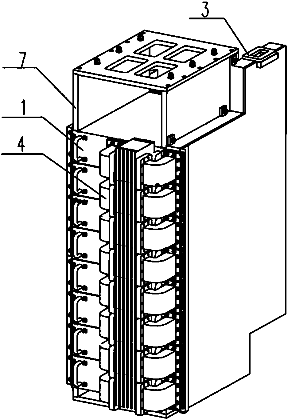
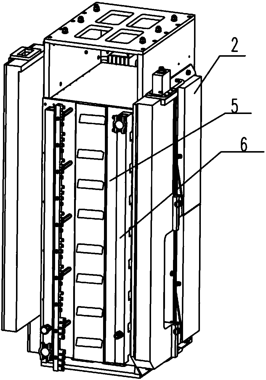
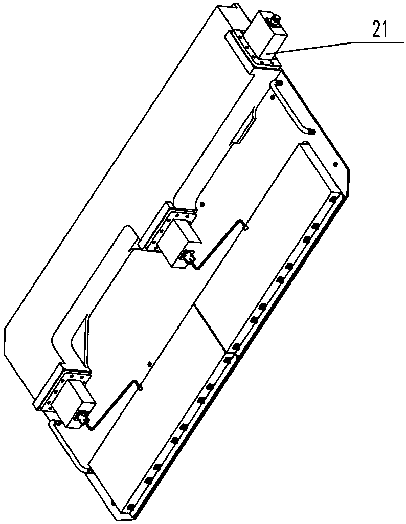
[0048] Such as Figure 1a with Figure 1b As shown, a cooling device for a high-power transmitter includes: a power module 1, a power splitter 2, a power combiner 3, a waveguide device 4, a socket board 5, a liquid diversity device 6 and a support frame 7, a power module 1, The power divider 2, the power combiner 3, the waveguide device 4, the socket board 5 and the liquid divider 6 are arranged on the support frame 7. The power divider 2 is connected to the power module 1, and the power module 1 is connected to the power combiner 3 through the waveguide device 4. After the signal enters the power divider 2, the power divider 2 divides the signal into multiple channels and inputs them to multiple power modules 1 , The multipl...


PUM


Abstract

The invention relates to a high-power transmitter cooling apparatus. The high-power transmitter cooling apparatus comprises a plurality of power modules, a power combiner and liquid dividers; pipelines used for coolant circulation are formed in the multiple power modules and the power combiner; each liquid divider is provided with an external connector, a power combining connector and a pluralityof power connectors; each liquid divider is connected with the pipeline in the power combiner through the power combining connector; each liquid divider is connected with the pipelines in the multiplepower modules through the multiple power connectors separately; and after each liquid divider performs coolant exchange with the power modules and the power combiner, the liquid divider is connectedwith the outside through the corresponding external connector so as to take away the heat of the power modules and the power combiner. The pipelines used for coolant circulation are formed in the multiple power modules and the power combiners with concentrated heat, and the coolant is connected with the outside through the external connectors, so that the parts with concentrated heat can be subjected to heat dissipation, the heat generated in the working process of the transmitter can be taken away in time, and the efficiency and reliability of the transmitter can be ensured.

Description

Technical field [0001] The invention relates to the technical field of radar transmitters and the technical field of heat dissipation, in particular to a cooling device for a high-power transmitter. Background technique [0002] The transmitter plays an indispensable role in the application of radar technology. The high-power transmitter will generate a lot of heat during the working process, which will affect the working efficiency of the transmitter and even cause damage to the transmitter itself due to overheating. Therefore, the industry urgently needs to solve the problem of how to cool the high-power transmitter. Summary of the invention [0003] In order to overcome the above-mentioned shortcomings of the prior art, the present invention proposes a high-power transmitter cooling device, which can dissipate heat from components with concentrated heat, and timely take away the heat generated during the working process of the transmitter to ensure the efficiency and reliabili...

Claims


Application Information

Patent Timeline
IPC IPC(8): H05K7/20
CPCH05K7/20272
Inventor 章玉太
Owner BEIJING INST OF RADIO MEASUREMENT
Learn More