Semi-direct drive megawatt-level permanent-magnet windmill generator

A wind power generator, megawatt-level technology, applied in the field of semi-direct-drive megawatt-level permanent magnet wind power generators, can solve the problem of not being able to effectively ensure that the temperature rise of the motor meets the requirements, high processing, process installation requirements, and difficult tightness of the iron core Adjustment and other issues to achieve the effect of prolonging the regular maintenance cycle, improving bearing insulation, and improving heat dissipation efficiency

Active Publication Date: 2011-04-06
DONGFANG ELECTRIC MACHINERY
View PDF14 Cites 2 Cited by
  • Summary
  • Abstract
  • Description
  • Claims
  • Application Information

AI Technical Summary

Problems solved by technology

However, for permanent magnet synchronous wind turbines with relatively small shaft diameters, the above-mentioned ventilation structure obviously cannot effectively dissipate heat, and cannot effectively ensure that the temperature rise of the motor meets the requirements
[0006] 3. For the bearing insulation structure, the existing technology often uses insulating materials to isolate the connection between the bearing and the end cover. For example, the Chinese patent with the publication number CN101728894A and the publication date of June 9, 2010 discloses an insulating end cover. The insulating cover structure is provided with radial and axial insulating sleeves on the outer ring of the bearing. The

Method used


Image

  • Semi-direct drive megawatt-level permanent-magnet windmill generator
  • Semi-direct drive megawatt-level permanent-magnet windmill generator
  • Semi-direct drive megawatt-level permanent-magnet windmill generator

Examples


Embodiment 1

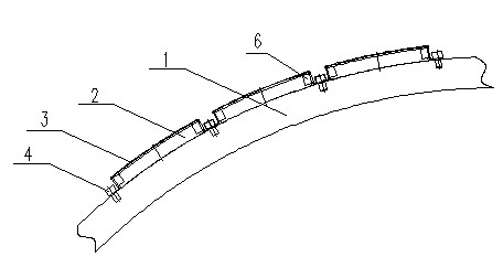
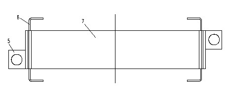
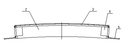
[0056] The invention discloses a semi-direct drive megawatt-level permanent magnet wind power generator, which includes a permanent magnet fixing structure, a cooling and ventilation structure, a bearing insulation structure and a stator core compression structure, such as Figure 1~3 As shown, the permanent magnet fixing structure includes a magnetic steel fixing frame 3 and stainless steel bolts 4 for installing the permanent magnet 2, the bottom 7 of the magnetic steel fixing frame 3 is closely attached to the permanent magnet 2, and the magnetic steel fixing frame 3 The connecting ears 5 at both ends of the bottom 7 are provided with through holes for matching with the stainless steel bolts 4, the magnetic steel fixing frame 3 is connected with the rotor cylinder 1 through the stainless steel bolts 4, and the material of the magnetic steel fixing frame 3 is stainless steel .

[0057] The permanent magnet 2 is installed in the magnetic steel fixing frame 3, and the bottom 7...

Embodiment 2

[0061] On the basis of Example 1, another preferred embodiment of the present invention is as follows: as Figure 4~9 As shown, the cooling ventilation structure includes a cooler 1, a cover plate 2, a partition 3, a frame arc plate 4, a rib plate 5 and a stator core 6; wherein, the cooler 1 is placed on the top of the motor, and the cylindrical frame arc The plate 4 is placed outside the stator core 6, the cover plate 2 is placed outside the frame arc plate 4, the partition plate 3 is located between the frame arc plate 4 and the cover plate 2, and the partition plate 3 connects the frame arc plate 4 and The area between the cover plates 2 is separated into two wind areas that are not ventilated in the axial direction. In the wind area, multiple groups of radial ventilation holes are evenly distributed along the circumferential direction on the frame arc plate 4 , and multiple axial ribs 5 are installed between the frame arc plate 4 and the stator core 6 . A plurality of rib...

Embodiment 3

[0064] On the basis of Examples 1 and 2, a preferred embodiment of the present invention is: as Figure 10~11 As shown, the bearing insulation structure includes a bearing 1 installed on the bearing sleeve of the main shaft of the generator, two insulating rings installed on both axial ends of the bearing 1, an insulating steel ring arranged on the outer ring of the bearing 1, and a bearing used to fix the bearing 1. The bolts 8 of the inner cover and the outer cover, the bolts 8 penetrate into the insulating sleeve 6 through the insulating washer 5, and the insulating sleeve 6 runs through the two insulating rings.

[0065] The present invention consists of a bearing 1 installed on the bearing sleeve of the main shaft of the generator, insulating rings on both ends of the axial direction of the bearing 1, a steel ring 3 of the outer ring of the bearing 1 and an outer insulating layer 4 of the steel ring 3, and fixing bolts 8 of the inner and outer covers. Between the insulati...


PUM


Abstract

The invention discloses a semi-direct drive megawatt-level permanent-magnet windmill generator which relates to the technical field of windmill generators. The semi-direct drive megawatt-level permanent-magnet windmill generator comprises a permanent magnet fixing structure, a cooling ventilation structured bearing insulating structure and a stator core compaction structure, wherein the permanent magnet fixing structure comprises a magnetic steel fixed mount and a stainless steel bolt, and the magnetic steel fixed mount is used for installing the permanent magnet; the bottom of the magnetic steel fixed mount is closely laminated with the permanent magnet; joint lugs on both ends of the bottom of the magnetic steel fixed mount are provided with through holes which are matched with the stainless steel bolt; and the magnetic steel fixed mount is connected with a rotor cylinder through the stainless steel bolt. In the invention, the defect of unfirm fixation of the prior high-power surface type permanent-magnet rotor permanent magnet on the rotor is overcome, thereby ensuring the reliability and efficiency of the generator, and the defects in the prior ventilation structure is also overcome, thereby increasing the length of the wind path, enhancing the heat elimination efficiency and further effectively lowering the operation temperature rise of the motor.

Description

[0001] technical field [0002] The invention relates to the technical field of wind power generators, in particular to a semi-direct drive megawatt permanent magnet wind power generator. Background technique [0003] A permanent magnet wind turbine usually includes components such as a generator stator, a rotor, and an outlet box. In addition, permanent magnet fixing parts, magnetic steel assembly tools, cooling ventilation parts, insulating bearings, and stator core compression structures are also required. The existing permanent magnet generator has the following disadvantages: [0004] 1. For the fixing structure of the surface magnet of the permanent magnet wind power generator, a new type of surface permanent magnet fixing method has appeared in the prior art, such as the Chinese patent with the publication number CN2840480 and the publication date being November 22, 2006 The literature discloses a surface-type permanent magnet fixing method. The technical soluti...

Claims


Application Information

Patent Timeline
IPC IPC(8): H02K1/28H02K9/10H02K5/20H02K5/16H02K1/12H02K9/19
Inventor 李松田齐智镝
Owner DONGFANG ELECTRIC MACHINERY
Why Eureka
Try Eureka