Aerial camera with fault protection function

A fault protection, aerial photography technology, applied in the field of aerial photography, aerial photography with fault protection function, can solve problems such as damage to shooting equipment, damage to aerial photography equipment, direct drop, etc., to achieve the effect of rapid extraction and avoidance of damage

Inactive Publication Date: 2018-04-17
广西防城港美达电子科技有限公司
View PDF0 Cites 0 Cited by
  • Summary
  • Abstract
  • Description
  • Claims
  • Application Information

AI Technical Summary

Problems solved by technology

[0003] None of the existing aerial photography equipment is equipped with a fault protection device, which makes the aerial photography equipment fall directly once it is damaged in the air, not only the aerial photography equipment will be damaged, but also the shooting equipment will be damaged accordingly

Method used


Image

  • Aerial camera with fault protection function
  • Aerial camera with fault protection function
  • Aerial camera with fault protection function

Examples


Embodiment 1

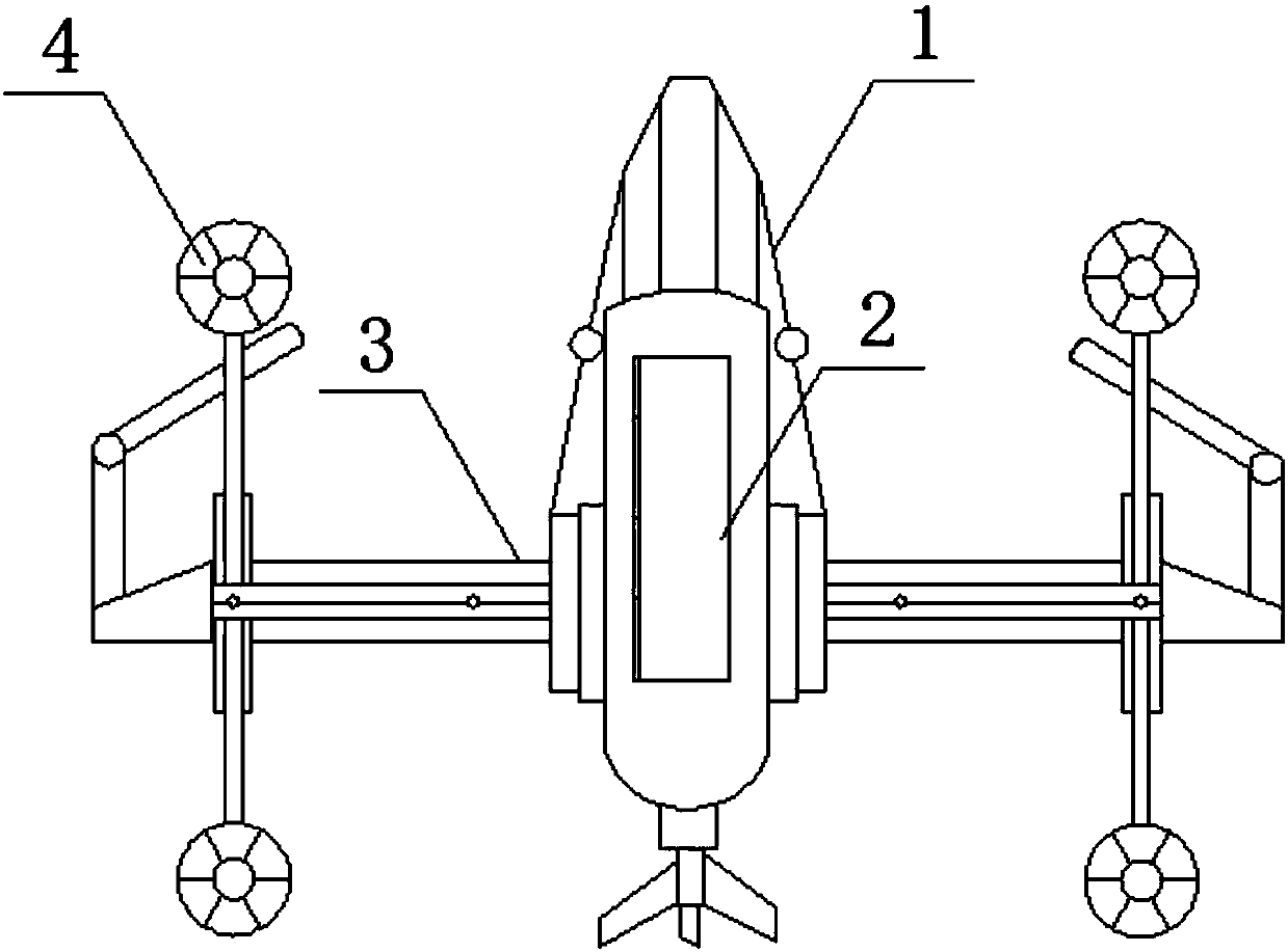
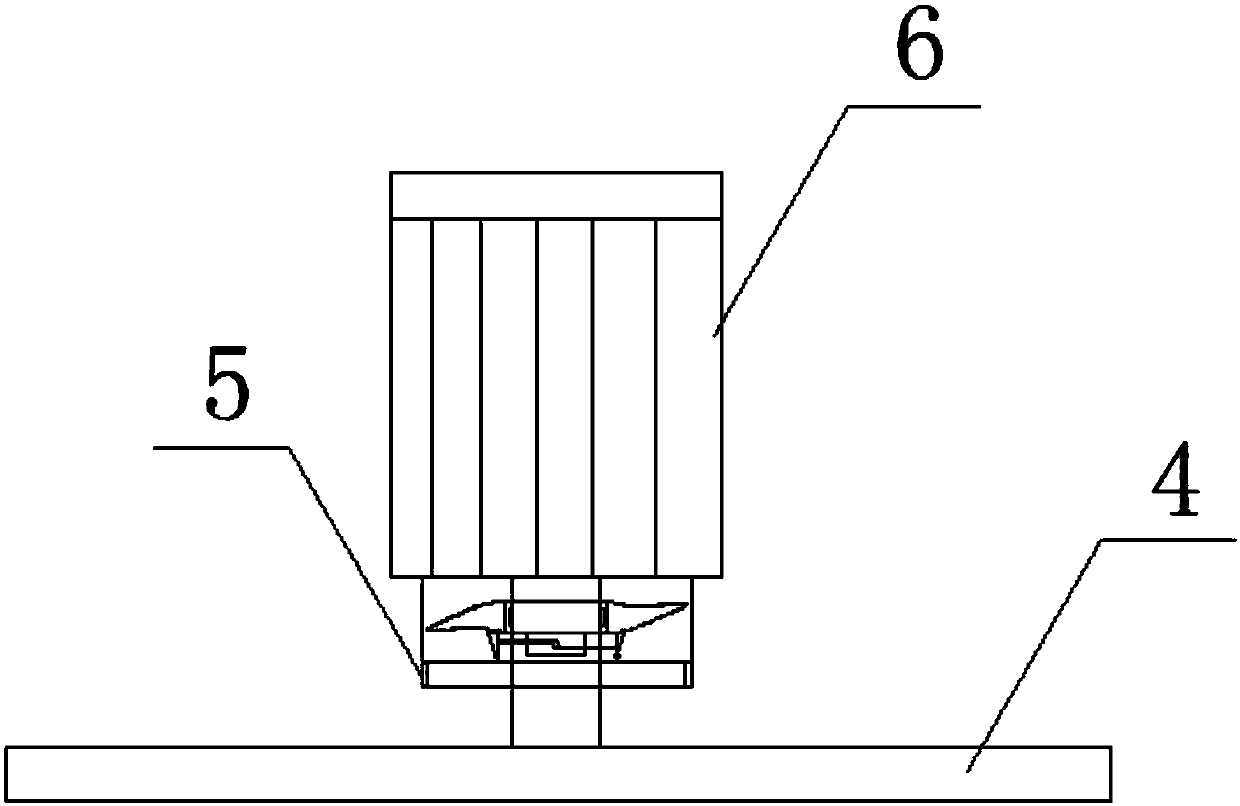
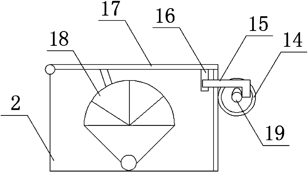
[0024] see Figure 1-5 As shown, an aerial photography machine with a fail-safe function includes a fuselage 1, a cabin 2, a wing 3 and a propeller 4, a cabin 2 is provided in the middle of the fuselage 1, and a parachute 18 is provided inside to protect the equipment in case of failure. , and both sides of the fuselage 1 are equipped with wings 3 to carry the propeller 4, and both sides of the wing 3 are provided with a motor 6 to provide power for the propeller 4, and one end of the motor 6 is installed with a motor shaft 7, which can effectively transmit power , the outer side of the motor shaft 7 is set with an induction mechanism 5, which can sense the situation that the propeller 4 stops rotating, and react accordingly, and the bottom of the motor shaft 7 is equipped with a propeller 4, which can rotate to provide lifting force, and the two sides of the upper part of the motor shaft 7 Both are equipped with a block 8, which can block the metal fan 11 when the motor shaft...

Embodiment 2

[0026] see Figure 1-5 As shown, the difference from Embodiment 1 is that the middle part of the metal fan 11 is an annular structure, and the inner side wall of the environmental structure of the middle part of the metal fan 11 is provided with a groove that matches the stopper 9, which can be driven when the motor shaft 7 rotates. The metal fan 11 rotates, and when the motor shaft 7 does not rotate, the metal fan 11 will fall and fall into the receiving groove 13 to act as a conductor; Effectively pull the bar 15 away from the collar 16 quickly and accurately to open the hatch 17; the relay box 12 is electrically connected to the micro-motor 14, which can effectively and accurately transmit the electric energy of the induction mechanism 5 to the micro-motor 14, The micro-motor 14 is rotated to open the hatch 17; the middle part of the storage box 10 is provided with a knob, and the knob at the middle part of the storage box 10 is connected to the stopper 9 through a wire, so...


PUM


Abstract

The invention disclose an aerial camera with a fault protection function, comprising a body, a cabin, wings, a propeller, a sensing mechanism, a motor, a motor shaft, a fixture block, a check block, astorage box, a metal fan, a relay box, a carrying slot, a micromotor, a barrier strip, a lantern ring, a cabin door, a parachute and a shifting block. The aerial camera has the beneficial effects that the middle of the metal fan is of an annular structure, a groove matched with the check block is formed in the side wall of the inner side of the annular structure of the middle of the metal fan, the metal fan can be driven to rotate when the motor shaft rotates, and when the motor shaft rotates, the metal fan falls off and drops into the carrying slot to be used as a conductor; one side of theshifting block is of a semicircular structure, and the other side is of an oval structure, so that the barrier strip can be rapidly and accurately pulled away from the lantern ring to open the cabin door; and the relay box is electrically connected to the micromotor, and electric energy of the sensing mechanism can be effectively and accurately transmitted to the motor, so that the motor rotates and opens the cabin door.

Description

technical field [0001] The invention relates to an aerial photography machine, in particular to an aerial photography machine with a fault protection function, and belongs to the field of aerial photography equipment. Background technique [0002] Aerial photography, also known as aerial photography or aerial photography, refers to taking pictures of the earth's landforms from the air to obtain a top view. This picture is an aerial photo. Aerial cameras can be controlled by the photographer, or they can be shot automatically or remotely. The platforms used for aerial photography include aircraft models, airplanes, helicopters, hot air balloons, small spaceships, rockets, kites, parachutes, etc. [0003] Existing aerial photography equipment is not equipped with a fail-safe device, which makes the aerial photography equipment once damaged in the air, will directly fall, not only the aerial photography equipment will be damaged, but also the shooting equipment will be damaged...

Claims


Application Information

Patent Timeline
Patent Type & Authority Applications(China)
IPC IPC(8): B64C39/02B64D17/80
CPCB64C39/02B64D17/80B64U2101/30B64U70/83
Inventor 刘斌和
Owner 广西防城港美达电子科技有限公司
Why Eureka
Try Eureka