
Motor blocking stator structure, motor stator and motor

A block stator, motor stator technology, applied in the direction of magnetic circuit shape/style/structure, winding insulation shape/style/structure, electrical components, etc., can solve the problem of increased motor temperature rise, reduced mold life, stator core iron Increased motor loss and other issues to achieve the effect of improving motor efficiency, simple structure, and reducing iron loss

Pending Publication Date: 2018-04-17
ZHUHAI GREE REFRIGERATION TECH CENT OF ENERGY SAVING & ENVIRONMENTAL PROTECTION
View PDF0 Cites 3 Cited by
  • Summary
  • Abstract
  • Description
  • Claims
  • Application Information

AI Technical Summary

Problems solved by technology

For example, in the buckle riveting, the buckle riveting needs to be buckled at the outer diameter of the stator core, so that there is a large height difference between the inner and outer diameters of the stator punching; while welding (such as laser welding or argon arc welding), buckle point riveting Destroying the insulation of the silicon steel sheet increases the iron loss and temperature rise of the motor
In addition, welding will damage the insulation structure of the silicon steel sheet, and the iron loss of the stator core will increase, which will increase the temperature rise of the motor; the buckle point riveting will be sharply worn due to the stress concentration due to the small buckle point. Die life is greatly reduced

Method used


Image

  • Motor blocking stator structure, motor stator and motor
  • Motor blocking stator structure, motor stator and motor
  • Motor blocking stator structure, motor stator and motor

Examples


Embodiment Construction

[0027] The present invention is described below based on examples, but the present invention is not limited to these examples. In the following detailed description of the invention, some specific details are set forth in detail. The present invention can be fully understood by those skilled in the art without the description of these detailed parts. To avoid obscuring the essence of the present invention, well-known methods, procedures, procedures, and components have not been described in detail.

[0028] Additionally, those of ordinary skill in the art will appreciate that the drawings provided herein are for illustrative purposes and are not necessarily drawn to scale.

[0029] Unless the context clearly requires, throughout the specification and claims, "comprises", "comprises" and similar words should be interpreted in an inclusive sense rather than an exclusive or exhaustive meaning; that is, "including but not limited to" meaning.

[0030] In the description of the ...


PUM


Abstract

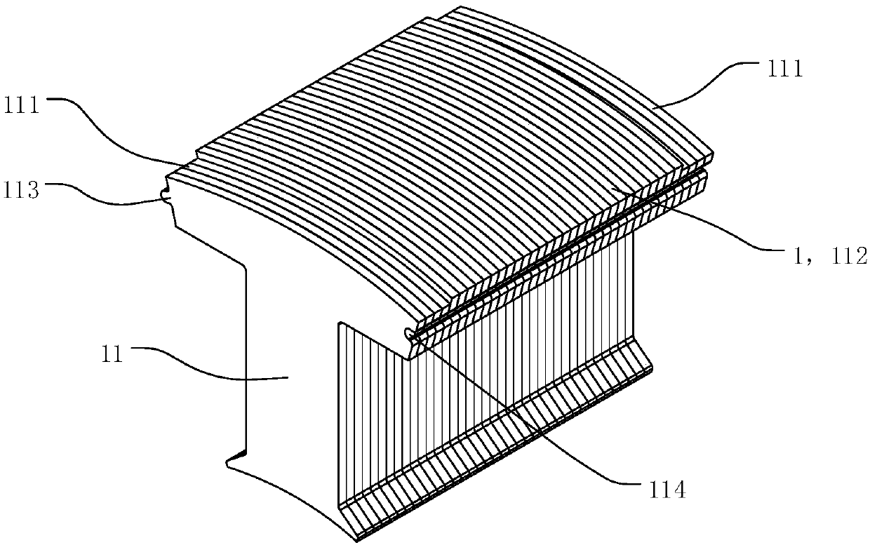
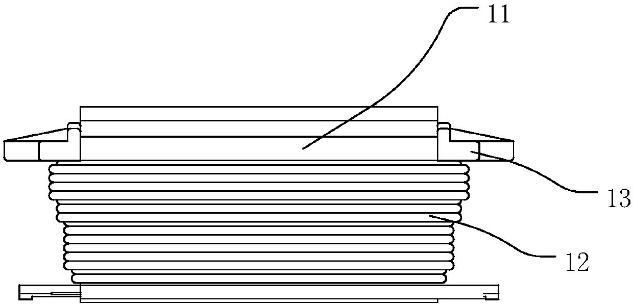
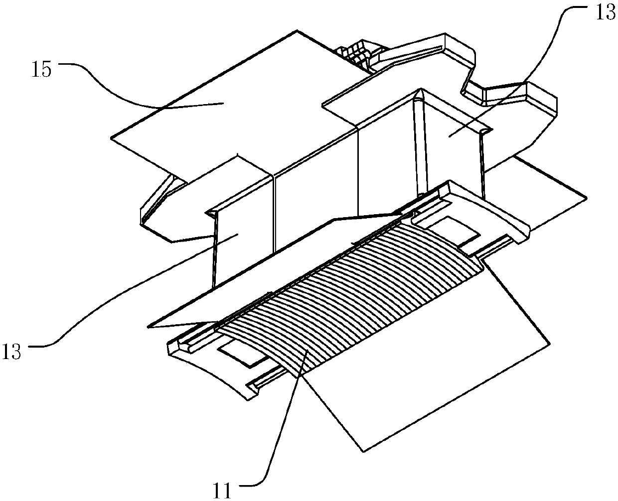
The invention discloses a motor blocking stator structure, a motor stator with the motor blocking stator structure and a motor. The motor blocking stator structure includes a plurality of mutually independent stator punching sheets which are stacked together, wherein the plurality of stator punching sheets are fixed together through coiling. In the motor blocking stator structure, the plurality ofstacked stator punching sheets are fixed together through coiling; no other fixed structures are arranged among the plurality of stator punching sheets; and the stacked stator punching sheets are fixed together only through winding of coiling; and the plurality of blocking stator structures are fastened and fixed through fastening rings to realize firm fixing of the overall motor stator. The motor blocking stator structure can effectively reduce the iron core loss of the stator core, can improve efficiency of the motor and can reduce temperature rise of the motor.

Description

technical field [0001] The invention relates to the technical field of motors, in particular to a block stator structure of a motor, a motor stator and a motor provided with the block stator structure. Background technique [0002] The traditional motor stator core generally adopts a monolithic or segmented splicing structure. Whether it is an integral or block splicing structure, most of the stator punchings are fixed together by welding, buckle riveting, buckle point riveting, etc. to meet the technical needs. For example, in the buckle riveting, the buckle riveting needs to be buckled at the outer diameter of the stator core, so that there is a large height difference between the inner and outer diameters of the stator punching; while welding (such as laser welding or argon arc welding), buckle point riveting The insulation of the silicon steel sheet is destroyed, which increases the iron consumption and temperature rise of the motor. In addition, welding will damage th...

Claims


Application Information

Patent Timeline
Patent Type & Authority Applications(China)
IPC IPC(8): H02K1/14H02K3/34
CPCH02K1/148H02K3/345H02K2201/15
Inventor 谭建明胡余生刘吉胜钟成堡肖胜宇郝福刚李昊
Owner ZHUHAI GREE REFRIGERATION TECH CENT OF ENERGY SAVING & ENVIRONMENTAL PROTECTION
Learn More