Carrier signal testing device and testing method

A carrier signal, testing device technology, applied in transmission monitoring, electrical components, transmission systems, etc., can solve the problems of large interference amplitude, complex interference waveform, wide frequency range of power line noise, etc., to achieve good detection effect, high efficiency, wide range The effect of suitability

Pending Publication Date: 2018-04-17
STATE GRID JIANGSU ELECTRIC POWER CO ELECTRIC POWER RES INST +2
View PDF5 Cites 2 Cited by
  • Summary
  • Abstract
  • Description
  • Claims
  • Application Information

AI Technical Summary

Problems solved by technology

[0002] In addition to the transmission power, the carrier communication distance is also related to the dynamic range and anti-interference ability of the carrier receiving device under test, because the attenuation of the carrier signal by the low-voltage power line is from 20dB to more than 80dB, and the noise frequency range of the power line is wide, and the interference amplitude is large , the interference waveform is complex and changes with time, and there are various SNR environments. Although the DL / T698-1999 and Q / GDW374.3-2008 standards do not specify the specific parameters of the carrier reception capability, according to Communication Principles Receiving sensitivity and anti-interference also affect the success rate of communication. It is necessary to evaluate the communication ability of the receiver under different signal-to-noise ratio conditions, as well as the communication ability of the receiver under various noise interference with different characteristics.

Method used


Image

  • Carrier signal testing device and testing method

Examples


Embodiment Construction

[0030] The present invention will be specifically introduced below in conjunction with the accompanying drawings and specific embodiments.

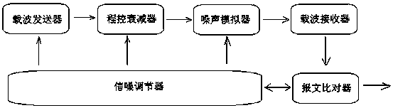
[0031] A carrier signal testing device, comprising a signal-to-noise conditioner, a carrier transmitter, a program-controlled attenuator, a noise simulator, a carrier receiver, and a message comparator connected in series;

[0032] The signal-to-noise conditioner generates signal-to-noise messages, including data messages provided to the carrier transmitter and message comparator, attenuated signals provided to the programmable attenuator, and noise signals provided to the noise simulator.

[0033] The carrier transmitter generates and sends the carrier signal according to the data message; the program-controlled attenuator and the noise simulator adjust the strength of the carrier signal and add interference noise according to the attenuation signal and the noise signal in turn; the message comparator according to the data message and the...


PUM


Abstract

The invention discloses a carrier signal testing device and a testing method, the carrier signal testing device comprises a signal noise adjustor, and a carrier transmitter, a programmable attenuator,a noise simulator, a carrier receiver and a message comparator orderly connected in series; the signal noise adjustor generates a signal noise message which comprises a data message, an attenuation signal and a noise signal; the carrier transmitter generates a carrier signal according to the data message and transmits the carrier signal; the programmable attenuator adjusts strength of the carriersignal according to the attenuation signal; the noise simulator adds an interference signal to the carrier signal according to the noise signal; the carrier receiver receives the carrier signal and demodulates the data message; and the message comparator generates a comparison result according to the data message and the demodulated data message, and feeds back the comparison result to the signalnoise adjustor. The carrier signal testing device has the advantages of simple structure, clear detection result, random and non-single detection content, closed-loop cycling detection process, gooddetection effect, high efficiency, very high practicability and wide applicability.

Description

technical field [0001] The invention relates to a carrier signal test device and a test method, in particular to an automatic test device and method for the receiving capability of a carrier receiver under different signal-to-noise ratio conditions. Background technique [0002] In addition to the transmission power, the carrier communication distance is also related to the dynamic range and anti-interference ability of the carrier receiving device under test, because the attenuation of the carrier signal by the low-voltage power line is from 20dB to more than 80dB, and the noise frequency range of the power line is wide, and the interference amplitude is large , the interference waveform is complex and changes with time, and there are various SNR environments. Although the DL / T698-1999 and Q / GDW374.3-2008 standards do not specify the specific parameters of the carrier reception capability, according to Communication Principles Receiving sensitivity and anti-interference als...

Claims


Application Information

Patent Timeline
Patent Type & Authority Applications(China)
IPC IPC(8): H04B17/336
CPCH04B17/336
Inventor 龚丹穆小星徐晴刘建邹宁袁晓冬田正其周超祝宇楠
Owner STATE GRID JIANGSU ELECTRIC POWER CO ELECTRIC POWER RES INST
Why Eureka
Try Eureka