
Grinding device used for solid waste recovery

A technology of solid waste and pressing rollers, which is applied in the direction of grain processing, etc., can solve the problems that affect the efficiency of equipment rolling, waste extrusion splashing, scattering, etc., and achieve the effect of safety and stability of the overall structure

Inactive Publication Date: 2018-04-20
FOSHAN TIANSHUN TECH CO LTD
View PDF6 Cites 2 Cited by
  • Summary
  • Abstract
  • Description
  • Claims
  • Application Information

AI Technical Summary

Problems solved by technology

[0003] However, the existing crushing devices for solid waste recovery still have certain defects in use. Because the waste materials will inevitably be squeezed and splashed during the crushing process, there is a certain danger, and because the crushed waste is used Waste materials are often left on the rollers of the rollers. The waste materials will not only affect the efficiency of the device, but also will be scattered everywhere if they are not cleaned up in time.

Method used


Image

  • Grinding device used for solid waste recovery
  • Grinding device used for solid waste recovery
  • Grinding device used for solid waste recovery

Examples


Embodiment 1

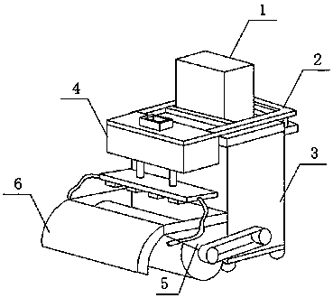
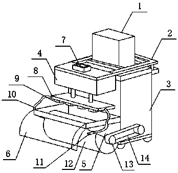
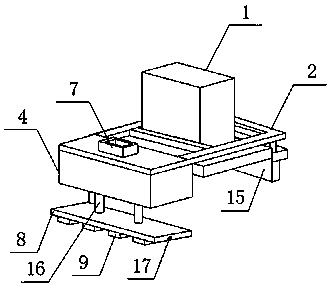
[0020] see Figure 1-3 As shown, a crushing device for solid waste recovery includes a chassis 3 and an underframe 5, a fixed frame 2 is installed on the top of the cabinet 3, a power supply box 1 is installed on the fixed frame 2, and a clamping plate 15 is arranged at one end of the fixed frame 2, The other end of the fixed frame 2 is installed with a water tank 4, the top of the water tank 4 is provided with a water inlet 7, and the bottom of the water tank 4 is connected to two connecting pipes 16, the connecting pipes 16 are connected to the spray frame 8, and several nozzles 9 are arranged at the bottom of the spray frame 8, and the two ends of the spray frame 8 Connecting holes 17 are all arranged, and the water pipes 10 are connected on the connecting holes 17, and the bottom frame 5 is arranged on the side wall of the bottom of the cabinet 3; The waste material splashed during rolling is blocked to effectively prevent the material from splashing during rolling, and a ...

Embodiment 2

[0022] Please continue to refer to Figure 1-3 The difference between it and the above-mentioned embodiment is that the clamping plate 15 at one end of the fixed frame 2 is attached to the outer wall on one side of the top of the cabinet 3, and the water tank 4 at the other end of the fixed frame 2 is attached to the outer wall on the other side of the top of the cabinet 3. The water tank 4 is fixedly connected with the chassis 3 by using the fixing frame 2, so that the overall structure of the device is safer and more stable. The water tank 4 is connected with the water pump inside the cabinet 3 through pipelines, and the water tank 4 is connected with the spray rack 8 and the spray pipe 11 by pipelines. The spray frame 8 is facing the top of the pressure roller 12, and the nozzle of the nozzle 11 on the side wall of the bottom frame 5 is aligned with the inner wall of the baffle plate 6, and the water tank 4 is connected to the spray frame 8 facing the pressure roller throug...


PUM


Abstract

The invention discloses a grinding device used for solid waste recovery. The grinding device used for solid waste recovery comprises a power box, a fixing frame, a case, a water tank, a bottom frame,a baffle, a water inlet, a spraying frame, nozzles, water pipes, spraying pipes, a roller, a rotary shaft, a conveying belt, a clamping plate, connecting pipes and a connecting hole. The grinding device used for solid waste recovery has the beneficial effects that the baffle of an arc-shaped structure is installed on the side wall of the bottom frame and used for sheltering waste splashed in the grinding process of the roller, and thus the situation that waste is splashed when ground is effectively prevented; the water tank is installed at the top of the bottom frame and connected with the spraying frame right facing the roller through the two connecting pipes so that sundries adhering to the roller can be washed away by water sprayed out from the nozzles after the roller is used, and manual cleaning by workers is not needed; and the spraying pipes are obliquely installed on the outer walls of the two sides of the bottom frame and connected with the spraying frame through the water pipes, and the spraying pipes right face the inner wall of the baffle so that waste adhering to the baffle can be washed away by the spraying pipes after the baffle is used.

Description

technical field [0001] The invention relates to a crushing device, in particular to a crushing device for recycling solid waste, and belongs to the field of waste treatment. Background technique [0002] With the development and progress of the times, the garbage station has gradually developed from the previous manual garbage disposal to the degree of mechanized garbage disposal. Using garbage crushing equipment to crush garbage in large quantities at one time not only saves time, but also saves time. Manpower and material resources, greatly improving the processing efficiency. [0003] However, the existing crushing devices for solid waste recovery still have certain defects in use. Because the waste materials will inevitably be squeezed and splashed during the crushing process, there is a certain danger, and because the crushed waste is used Waste materials are often left on the rollers of the roller, which will not only affect the efficiency of the device and roller, bu...

Claims


Application Information

Patent Timeline
Patent Type & Authority Applications(China)
IPC IPC(8): B02C4/10B02C4/40
CPCB02C4/10B02C4/40
Inventor 朱远秋
Owner FOSHAN TIANSHUN TECH CO LTD
Learn More