
Novel cutting-off device for cutting off pouring gate

A cutting device, pouring gate technology, applied in sawing machine equipment, metal sawing equipment, maintenance and safety accessories, etc., can solve problems such as inability to use the cutting machine, no protection against debris, and dirty worktables

Pending Publication Date: 2022-03-18
YUTAKA ELECTRONICS SH
View PDF1 Cites 0 Cited by
  • Summary
  • Abstract
  • Description
  • Claims
  • Application Information

AI Technical Summary

Problems solved by technology

[0003] The main purpose of the present invention is to provide a new type of cutting device for cutting the pouring gate, which can effectively solve the problem that when there is an interference object in the direction of travel in the background technology, the existing cutting machine cannot be used for cutting, the applicability is low, and only It can correspond to simple product shapes, and when the screw rod and the nut seat are driven, it is easy to cause impact or impact at the end or limit position, and when the blade is sawing and pouring the casting, there is no device to prevent the cutting debris from splashing out on the side. , It is easy to cause the workbench to be dirty

Method used


Image

  • Novel cutting-off device for cutting off pouring gate
  • Novel cutting-off device for cutting off pouring gate
  • Novel cutting-off device for cutting off pouring gate

Examples


Embodiment 1

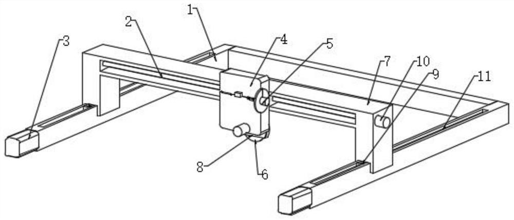
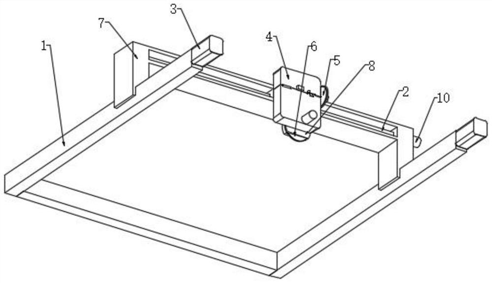
[0029] Such as Figure 1-7 As shown, a new type of cutting device for cutting the pouring mouth includes the first fixed frame 1, the cutting machine 6 and the second screw mandrel 11. In order to prevent the cutting machine 6 from interfering with the direction of travel, the existing cutting device cannot be used. Some cutting machines are used for cutting, which has low applicability and can only correspond to simple product shapes. A second fixing frame 7 is arranged between the first fixing frames 1, and a first screw rod 2 is arranged inside the second fixing frame 7. Through the cooperation of the first screw mandrel 2 and the second screw mandrel 11, before use, the two first fixing frames 1 are installed at the pouring mouth, and the first driving motor 3 can drive the first fixing frame 1 in the first fixing frame 1 at this time. The second screw mandrel 11 rotates, so that the second fixed mount 7 moves along the second screw mandrel 11, and the stand 4 is driven by...

Embodiment 2

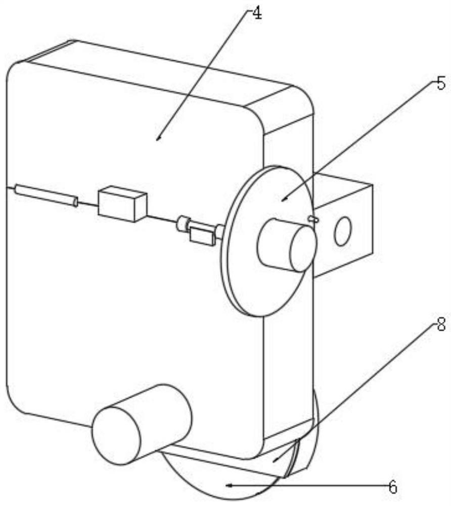
[0031] Such as image 3 and 4As shown, a new type of cutting device for cutting the pouring gate. In order to cut pouring gates with different orientations, a limit block 504 is arranged on the stand 4, and the angle between the limit block 504 and the first fixing plate 506 is 90°. °, the rotating disk 501 is provided with a rotating groove 503, and the rotating groove 503 is provided with two fixing holes and fixing pins, and the rotating motor 507 is located at the intersection of the stand 4 and the first fixing plate 506, cutting horizontally and vertically When the pouring port of the rotating disk 501 is pulled out from the fixing hole, the rotating shaft 502 is driven to rotate 90° by the flow stabilizer. Since the first fixing plate 506 rotates 90° around the rotating shaft 502, the fixing pin penetrates The fixing hole is fixed with the first fixing plate 506, the rotating disk 501 is welded on the side wall of the stand 4, the rotating shaft 502 is connected with t...

Embodiment 3

[0033] Such as Figure 5 As shown, a new type of cutting device for cutting the pouring port. In order to prevent the cutting debris from splashing out on the side of the blade when sawing the casting, it is easy to cause the workbench to be relatively dirty. The second fixing plate 802 One side is provided with a cover plate 801, the cover plate 801 is fixed to the second fixed plate 802 by bolts, and a first reserved hole 803 is arranged between the cover plates 801, and a first reserved hole 803 is provided on one side of the second fixed plate 802. Reserved groove 804, telescopic plate 807 is positioned in the first reserved groove 804, and telescopic plate 807 is provided with guide strip 806, and the inside of first reserved groove 804 is provided with the mating groove that cooperates with guide strip 806, in cutting When cutting, the telescopic plate 807 is slidably connected to the inside of the first reserved groove 804, and the guide bar 806 is slidably connected to...


PUM


Abstract

The novel cutting device comprises a first fixing frame, a cutting machine, a second fixing frame and a second lead screw, the first lead screw is arranged in the second fixing frame, a vertical frame is arranged on the second fixing frame, and the vertical frame is connected with the cutting machine through a rotating device. And the cutting machine comprises a motor and a saw blade, a protection device is arranged on the cutting machine, and a buffer device is arranged on the second lead screw in the first fixing frame. According to the novel cutting-off device for cutting off the pouring gate, the novel cutting-off device belongs to the technical field of die-casting dies, a cutting machine blade is used for cutting pouring gate castings in the vertical and horizontal directions, chippings generated during cutting of a cutting machine are shielded through a telescopic plate, and the situation that the chippings splash towards the side edge can be prevented; and chippings on a second lead screw can be cleaned through a cleaning piece and cleaning bristles at the lower end of a clamping block, and the function that the saw blade can move in a plane according to any track is achieved.

Description

technical field [0001] The invention relates to the technical field of die-casting molds, in particular to a novel cutting device for cutting a pouring port. Background technique [0002] The high-efficiency cutting of die-casting gates has far-reaching significance for ensuring the quality of die-castings. Large-scale die-casting gate high-speed cutting machine tools take high-speed cutting technology as the core, use machine tools as bridges, and integrate automated positioning, tracking gate positions, and Parts and other peripheral equipment to realize efficient automatic removal of die casting gates. In order to ensure the accuracy of die casting gate cutting, ensure the accuracy and quality stability of die castings, and achieve high-efficiency production, a new multi-axis cutting device can be used. The casting of the pouring port can be cut and broken. According to the patent number in the Chinese literature: CN201811357661.4, the patent name is "gate cutting device...

Claims


Application Information

Patent Timeline
Patent Type & Authority Applications(China)
IPC IPC(8): B23D45/00B23D47/04B23D47/12B23Q11/00B23Q11/08
CPCB23D45/00B23D47/04B23D47/12B23Q11/0042B23Q11/08
Inventor 张杨
Owner YUTAKA ELECTRONICS SH
Learn More