Workpiece main shaft capable of automatically dividing and clamping

An automatic indexing, workpiece spindle technology, applied in electric components, metal processing mechanical parts, driving devices, etc., can solve the problems of unsatisfactory braking effect, increased rotational inertia, insufficient braking force, etc., and achieve good braking effect. , strong thrust, compact structure

Pending Publication Date: 2018-04-20
GUANGZHOU QUNCHUANG CNC MACHINE TOOL CO LTD
View PDF9 Cites 6 Cited by
  • Summary
  • Abstract
  • Description
  • Claims
  • Application Information

AI Technical Summary

Problems solved by technology

[0002] The existing indexing spindle generally includes a detection device for detecting the rotation angle and a brake device for braking the spindle. Due to the large number of parts included, the structure is often more complicated, and the existing brake device generally adopts an electromagnetic system. Although it has a high response speed, the braking force is insufficient, and the weight of the spindle is generally heavy. After the workpiece is clamped, the rotational inertia is further increased, and the braking effect is often unsatisfactory.

Method used


Image

  • Workpiece main shaft capable of automatically dividing and clamping
  • Workpiece main shaft capable of automatically dividing and clamping
  • Workpiece main shaft capable of automatically dividing and clamping

Examples


Embodiment Construction

[0030] The preferred embodiments of the present invention will be described below in conjunction with the accompanying drawings. It should be understood that the preferred embodiments described here are only used to illustrate and explain the present invention, and are not intended to limit the present invention.

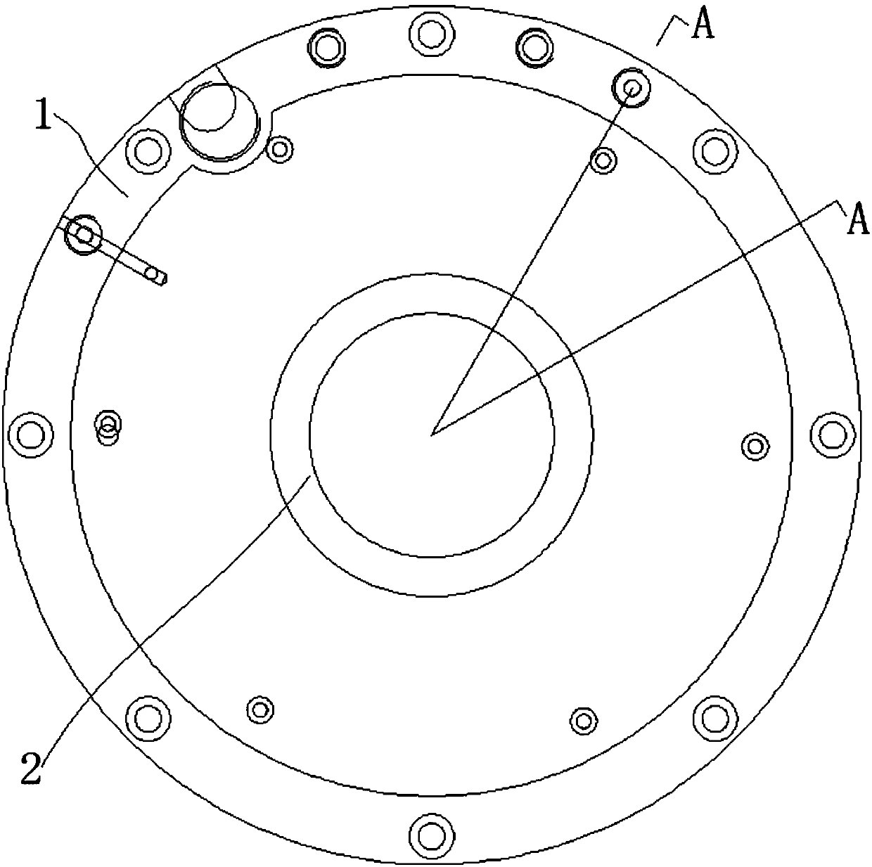
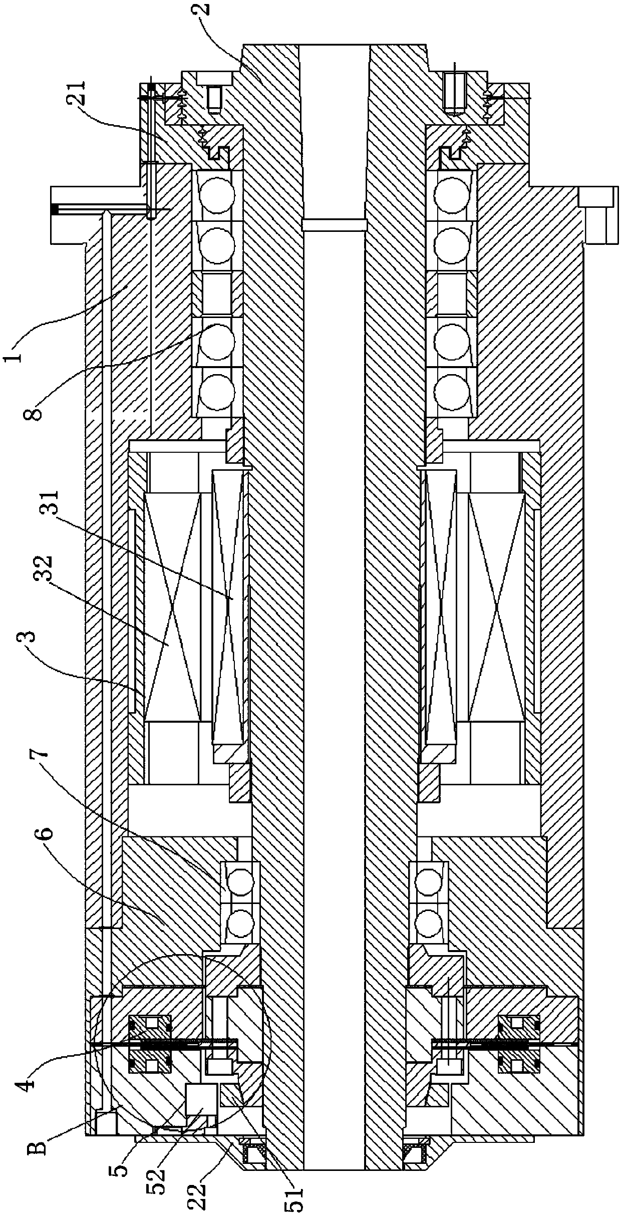
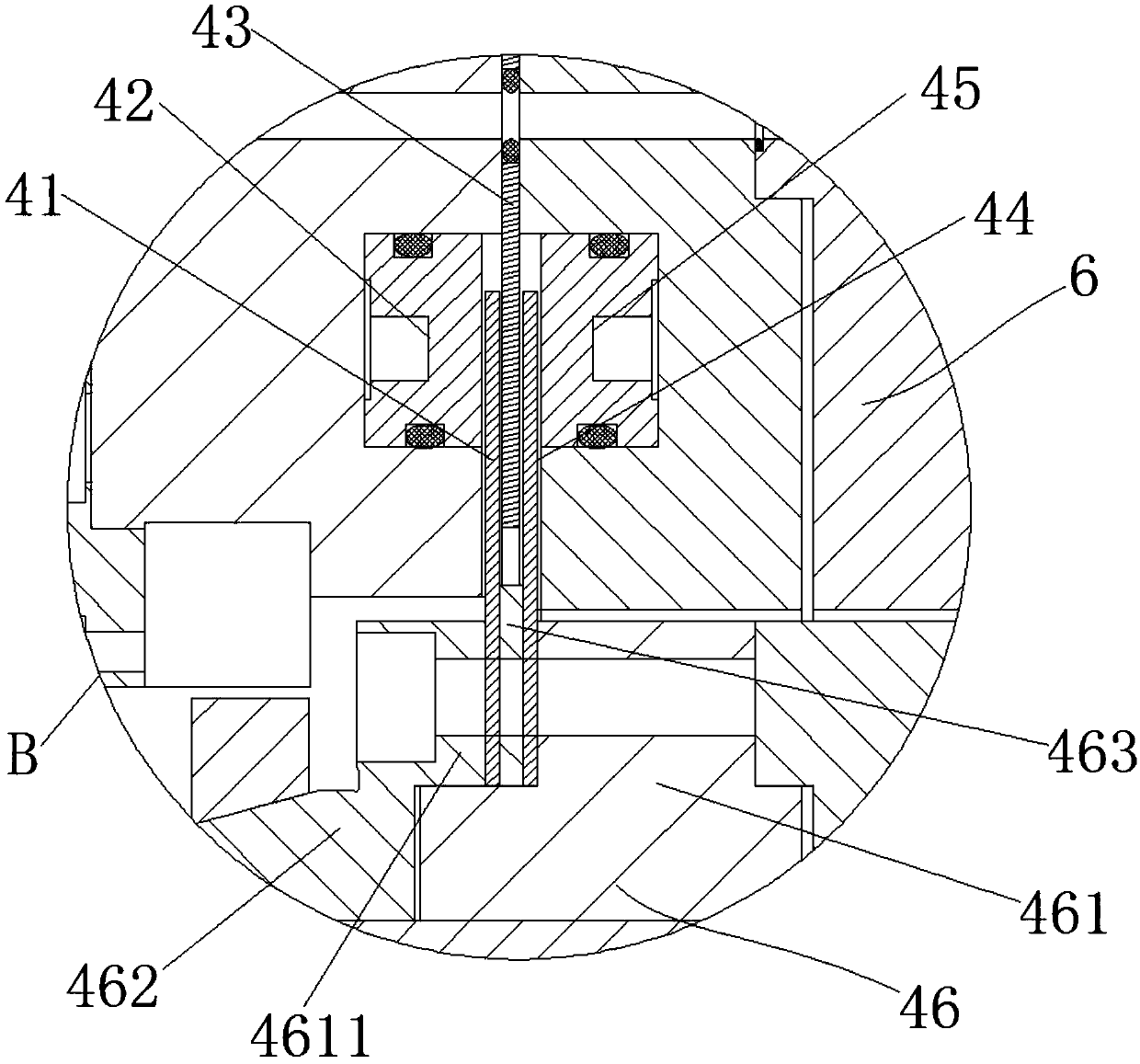
[0031] Such as Figure 1 ~ Figure 3 As shown, a workpiece spindle that can be automatically indexed and clamped according to the present invention includes a shaft sleeve 1, a shaft core 2, a motor 3, a clamping assembly 4 and an encoder assembly 5, and the shaft core 2 can pivotally Set in the shaft sleeve 1, the motor 3 is in transmission connection with the shaft core 2, and the motor 3 drives the shaft core 2 to rotate in the shaft sleeve 1. The clamping assembly 4 includes a brake disc 41, a first brake pad 42 and a first cylinder 43, the brake disc 41 is fixedly connected to the bushing 1, the first brake pad 42 is fixedly connected to the shaft core 2, the br...


PUM


Abstract

The invention discloses a workpiece main shaft capable of automatically dividing and clamping. The workpiece main shaft comprises a shaft sleeve, a shaft core and a motor, wherein the shaft core is pivotably arranged in the shaft sleeve; the motor is in transmission connection with the shaft core; the workpiece main shaft also comprises a clamping component used for braking the shaft core and an encoder component used for detecting rotation angles of the shaft core; the clamping component comprises a brake disc fixedly connected with the shaft sleeve, a first brake pad fixedly connected with the shaft core and a first cylinder fixedly connected with the shaft sleeve; a gap is reserved between the brake disc and the first brake pad; the first cylinder and the first brake pad are arranged onone side of the brake disc; a piston rod of the first cylinder directly faces to the first brake pad. When the shaft core needs to be braked, the piston rod of the first cylinder extends outwards andapplies pressure to the first brake pad; the first brake pad is stressed and deformed, and is in contact with the brake disc; the friction force between the first brake pad and the brake disc is capable of limiting the rotation of the shaft core; the pushing force of the cylinder is strong, so that a good braking effect can be ensured; the clamping component is few in parts; the workpiece main shaft is compact in structure and more convenient to assemble.

Description

technical field [0001] The invention belongs to the technical field of machine tool spindles, and in particular relates to a workpiece spindle capable of automatic indexing and clamping. Background technique [0002] The existing indexing spindle generally includes a detection device for detecting the rotation angle and a brake device for braking the spindle. Due to the large number of parts included, the structure is often more complicated, and the existing brake device generally adopts an electromagnetic system. Although it has a high response speed, the braking force is insufficient, and the weight of the spindle is generally heavy. After the workpiece is clamped, the rotational inertia is further increased, and the braking effect is often unsatisfactory. Contents of the invention [0003] In order to solve the above problems, the object of the present invention is to provide a workpiece spindle capable of automatic indexing and clamping, which has a compact structure a...

Claims


Application Information

Patent Timeline
Patent Type & Authority Applications(China)
IPC IPC(8): B23Q5/10H02K7/14
CPCH02K7/14B23Q5/10
Inventor 周意
Owner GUANGZHOU QUNCHUANG CNC MACHINE TOOL CO LTD
Why Eureka
Try Eureka