Biomass hot blast stove device

A hot blast stove and biomass technology, applied in lighting and heating equipment, combustion equipment, combustion methods, etc., can solve problems such as difficult cleaning, fuel bunker fire, low heat utilization rate, etc., achieve clean and thorough combustion, reduce dust emissions, The effect of saving fuel costs

Inactive Publication Date: 2017-01-11
SHUANGFENG ZHONGXIN TECH CO LTD
View PDF9 Cites 3 Cited by
  • Summary
  • Abstract
  • Description
  • Claims
  • Application Information

AI Technical Summary

Problems solved by technology

[0003] 1. The existing furnace body generally adopts single furnace (or double furnace) and four-return design. This design is direct combustion or incomplete gasification combustion, which is easy to produce tar and smoke. After running for a long time, the inner wall of the heating tube will condense Thick scorched scale is difficult to clean, affects heat conduction, lowers heat utilization rate, and is difficult to maintain in the future
[0004] 2. The existing fuel propulsion system mainly adopts spiral feeding. The biggest defect of this feeding method is: the fuel orientation is single (only biomass particles can be burned) and those hard fruit shells, bamboo and wood scraps (these Often high-quality biomass fuels with high calorie content and low price cannot be pushed forward, and problems such as jamming, blockage, and backfire to the fuel bunker are prone to occur during operation, which may easily cause a midway ceasefire and fire in the fuel bunker, etc.
[0005] 3. The main problem of the biomass hot blast stoves used by many users is that the welding joints of the furnace body are easy to burst, and the top of the furnace is easy to burn through
The reason for these problems is that the design of the air circulation system of the furnace body is unreasonable, and there are dead angles. The wind cannot reach these dead angles, and the heat cannot be dissipated in time. Oxidation at high temperature

Method used


Image

  • Biomass hot blast stove device
  • Biomass hot blast stove device
  • Biomass hot blast stove device

Examples


Embodiment Construction

[0022] To make the content of the present invention more clear and understandable, the content of the present invention will be further described below in conjunction with the accompanying drawings. Of course, the present invention is not limited to this specific embodiment, and general replacements known to those skilled in the art are also covered within the protection scope of the present invention. Secondly, the present invention is described in detail by means of schematic diagrams. When describing the examples of the present invention in detail, for the convenience of explanation, the schematic diagrams are not partially enlarged according to the general scale, which should not be used as a limitation to the type of the present invention.

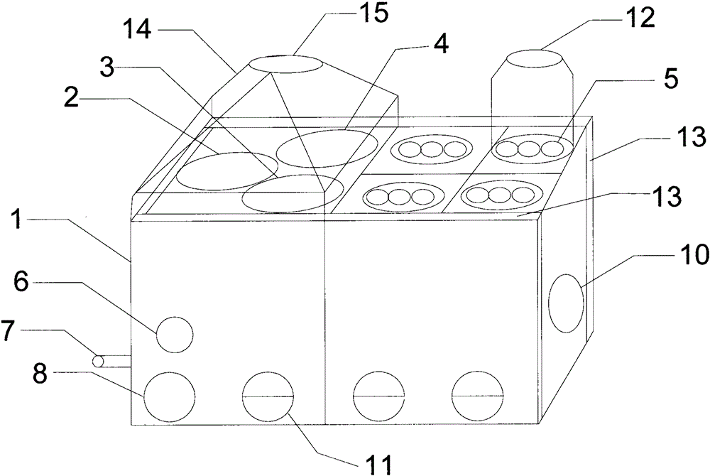
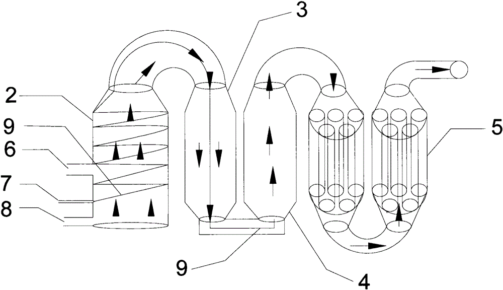
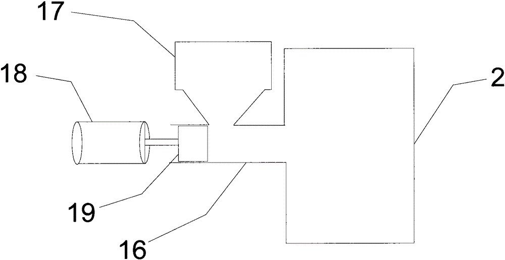
[0023] It should be noted that, in the following examples, using Figure 1~3 The schematic diagram of the structure describes in detail a kind of biomass hot stove equipment according to the present invention. When describing the emb...


PUM


Abstract

The invention discloses a biomass hot blast stove device. The biomass hot blast stove device comprises a stove body. A main hearth, a first auxiliary hearth, a second auxiliary hearth and an air heating tube are arranged in the stove body and communicate in sequence. A secondary oxygen supply blast nozzle is connected with the air heating tube. The air heating tube penetrates the main hearth and the first auxiliary hearth to enter the second auxiliary hearth. The stove body is provided with a fuel inlet, the secondary oxygen supply blast nozzle and a gasifying agent, wherein the fuel inlet, the secondary oxygen supply blast nozzle and the gasifying agent communicate with the main hearth. The stove body is further provided with a hot air outlet. The hot air outlet communicates with a heating tube. Air duct interlayers are arranged on the two sides of the stove body. Air conveying plates are arranged in the air duct interlayers. An air conveying cover is arranged on the upper side of the stove body. The air conveying cover is provided with an air conveying opening. The biomass hot blast stove device is high in heat utilization rate, capable of achieving clean and complete combustion, convenient to use, high in safety and good in heat radiating performance.

Description

technical field [0001] The invention relates to the field of heat energy equipment, in particular to a biomass hot stove equipment. Background technique [0002] The current biomass hot stove has the following defects: [0003] 1. The existing furnace body generally adopts single furnace (or double furnace) and four-return design. This design is direct combustion or incomplete gasification combustion, which is easy to produce tar and smoke. After running for a long time, the inner wall of the heating tube will condense Thick scorched scale is difficult to clean, which affects heat conduction, low heat utilization rate, and difficult to maintain in the future. [0004] 2. The existing fuel propulsion system mainly adopts spiral feeding. The biggest defect of this feeding method is: the fuel orientation is single (only biomass particles can be burned) and those hard fruit shells, bamboo and wood scraps (these High-quality biomass fuel with high calorie content and low price)...

Claims


Application Information

Patent Timeline
Patent Type & Authority Applications(China)
IPC IPC(8): F23B10/02F23K3/16
Inventor 王爱国
Owner SHUANGFENG ZHONGXIN TECH CO LTD
Why Eureka
Try Eureka