Electric automobile high-voltage power distribution system
A high-voltage power distribution and electric vehicle technology, applied in the field of automobile power distribution, can solve problems such as potential safety hazards and reduce the stability of high-voltage power distribution systems of electric vehicles, and achieve the effects of preventing potential safety hazards, improving stability and preventing damage.
- Summary
- Abstract
- Description
- Claims
- Application Information
AI Technical Summary
Problems solved by technology
Method used
Image

Examples
Embodiment Construction
[0025] In order to facilitate a better understanding of the present invention, the present invention will be further explained below in conjunction with the accompanying drawings of related embodiments. Embodiments of the invention are shown in the drawings, but the invention is not limited to the preferred embodiments described above. Rather, these embodiments are provided so that the disclosure of the invention will be more thorough.
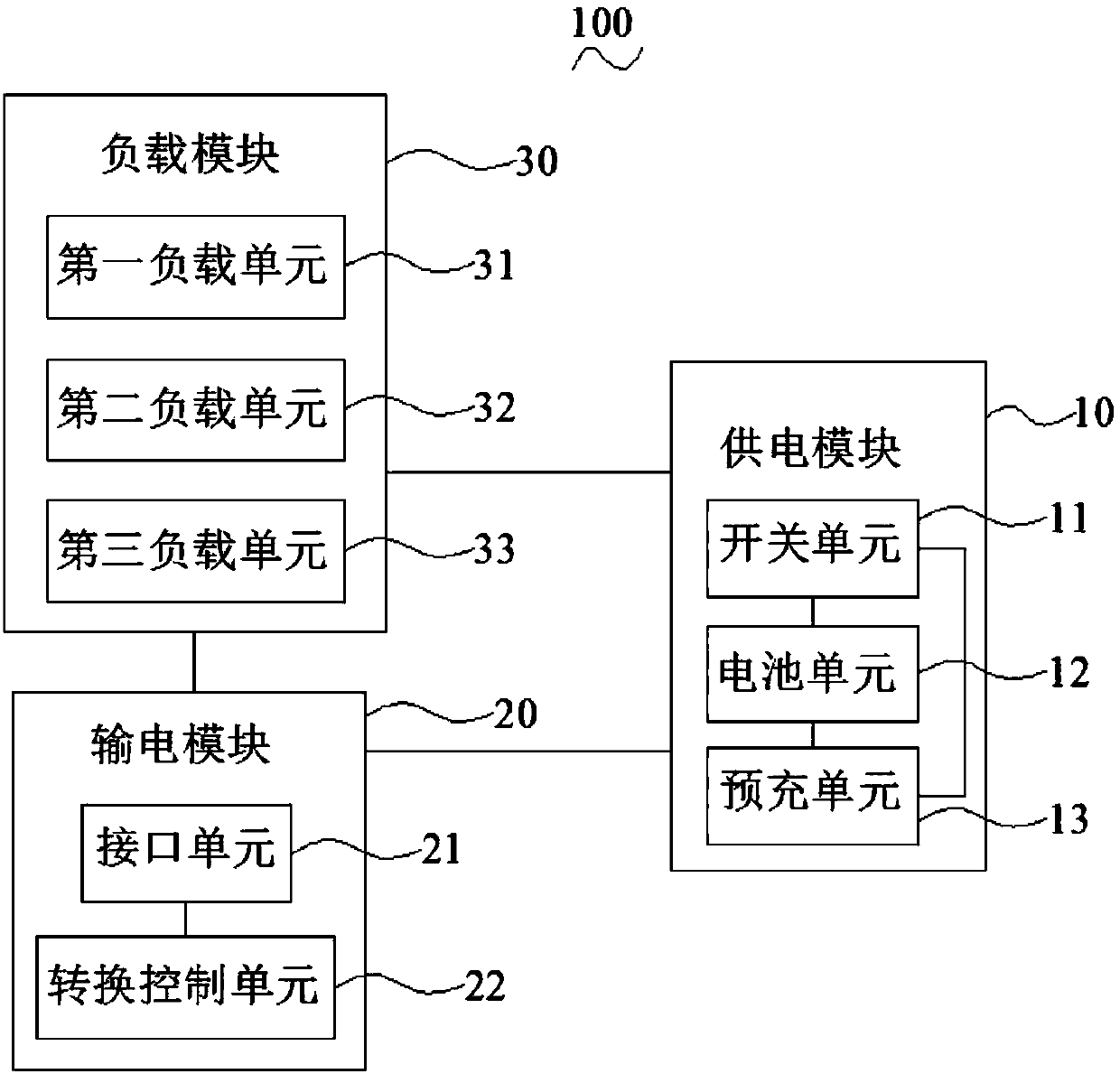
[0026] see figure 1 , is a schematic diagram of the module structure of the electric vehicle high-voltage power distribution system 100 provided in the first embodiment of the present invention, including a power supply module 10, a power transmission module 20 and a load module 30 electrically connected to the power supply module 10, and the power supply module 10 is used to supply power to the load module 30, so as to ensure the normal operation of various electrical equipment of the automobile, and the power transmission module 20 is used ...
PUM
 Abstract
Description
Claims
Application Information
 - Generate Ideas
- Intellectual Property
- Life Sciences
- Materials
- Tech Scout
- Unparalleled Data Quality
- Higher Quality Content
- 60% Fewer Hallucinations
Browse by: Latest US Patents, China's latest patents, Technical Efficacy Thesaurus, Application Domain, Technology Topic, Popular Technical Reports.
© 2025 PatSnap. All rights reserved.Legal|Privacy policy|Modern Slavery Act Transparency Statement|Sitemap|About US| Contact US: help@patsnap.com