High-speed high-efficiency tilt wing unmanned aerial vehicle

An unmanned aerial vehicle and a tilting wing technology, which is applied in the field of tilting wing vertical take-off and landing aircraft, can solve the problems of poor vertical flight heading control performance, low vertical flight rotor efficiency, insufficient rotor anti-torque heading control force, etc. The effect of improving control stability and improving battery life

Inactive Publication Date: 2018-04-20
北京天宇新超航空科技有限公司
View PDF5 Cites 15 Cited by
  • Summary
  • Abstract
  • Description
  • Claims
  • Application Information

AI Technical Summary

Problems solved by technology

Although the tilting wing unmanned aerial vehicle can meet the application requirements of some special scenarios, there are still problems such as low efficiency of the vertical flight rotor, slow level flight speed, and poor vertical flight heading control performance in practical applications.
For example: 1. The existing tilting wing unmanned aerial vehicles use the same power system for vertical flight and level flight, and most of them are fixed-pitch propellers. There are significant differences, which are determined by the different aerodynamic conditions of the propellers in different flight states. Therefore, the power system of the existing tilt-rotor unmanned aerial vehicle is difficult to be compatible with the vertical and horizontal flight states efficiently at the same time, and the horizontal flight speed is low; 2. The existing tilt-rotor unmanned aerial vehicle schemes mostly adopt multi-rotor vertical take-off and landing, and the heading control of the aircraft is realized through the control of the rotor speed or pitch. The control force of the control is obviously insufficient, which leads to poor wind resistance of this type of aircraft when flying vertically

Method used


Image

  • High-speed high-efficiency tilt wing unmanned aerial vehicle
  • High-speed high-efficiency tilt wing unmanned aerial vehicle
  • High-speed high-efficiency tilt wing unmanned aerial vehicle

Examples


Embodiment Construction

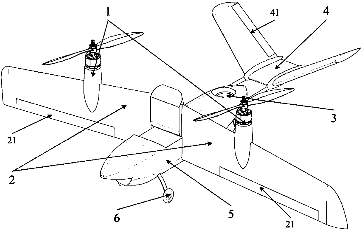
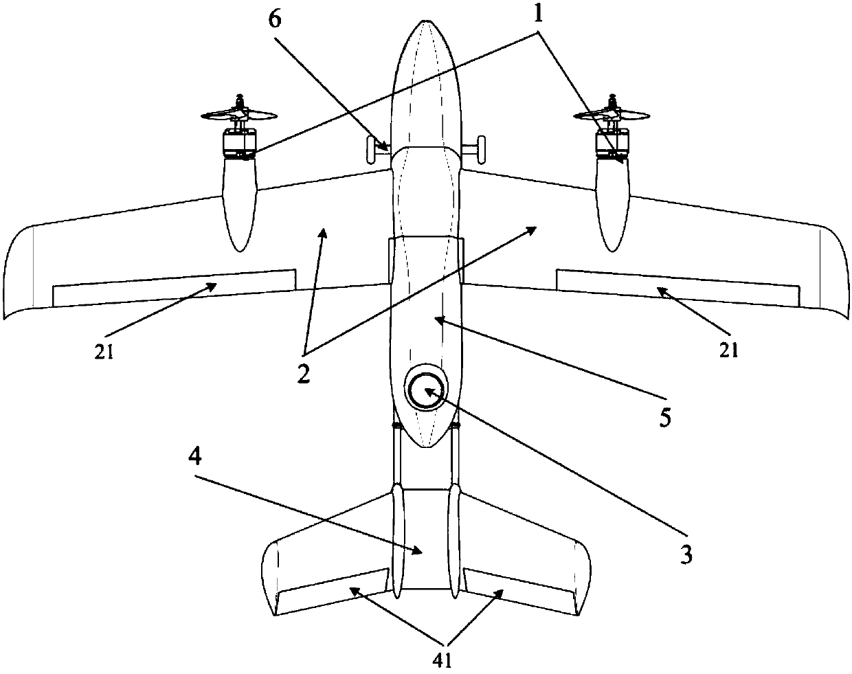
[0025] Figure 1~3 Shown is the basic structural layout and operation mode of a high-speed and high-efficiency tilting wing unmanned aerial vehicle of the present invention. The aircraft comprises: tilting rotor (1), tilting airfoil (2), tail culvert (3), fixed tail (4), fuselage structure (5) and landing gear (6), it is characterized in that, tail culvert The track is located between the tilting axis of the tilting rotor (1) and the empennage (4).

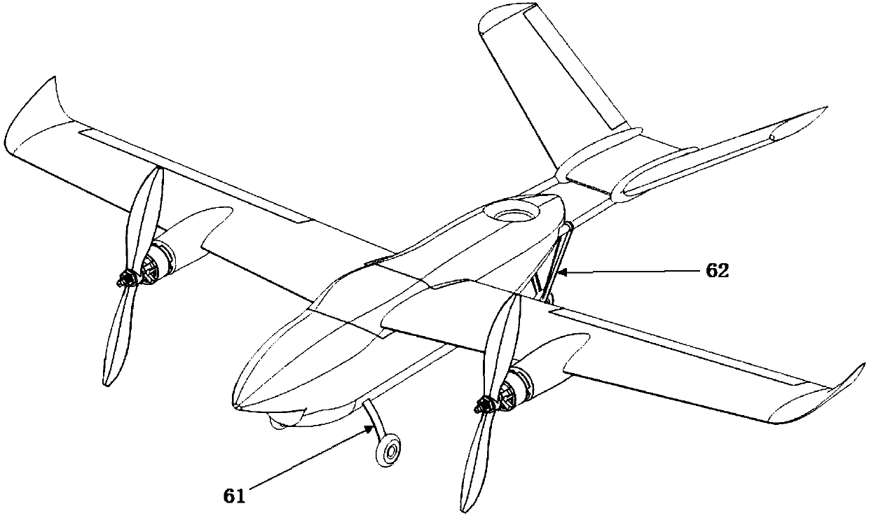
[0026] The aircraft should be able to fly in three flight states, including: vertical flight state, transition state and level flight state. figure 1 The relative positions of each tilting component (1) (2) and the fuselage structure (5) during the vertical flight state of the present embodiment are shown; figure 2 It is a schematic diagram of the level flight state of the embodiment; image 3 The relative position of each tilting part (1) (2) and the fuselage structure (5) in the level flight state of this embodiment is shown...


PUM


Abstract

The invention discloses a high-speed high-efficiency tilt wing unmanned aerial vehicle. The aerial vehicle layout has higher pneumatic efficiency and control reliability, can realize high speed and high efficiency flight on the premise of ensuring vertical take-off and landing. The aerial vehicle comprises tilting rotors, tilting airfoils, a tail duct, fixed empennages, a body structure and an undercarriage, wherein the tilting rotors and the tilting airfoils can rotate along rotating shafts through an actuating mechanism, and the tilting rotors have a variable range; and the tail empennages are variable thrust vectoring ducts. The aerial vehicle goes through a vertical flight state, transitional flight state and straight-and-level flight state from taking-off to level flight. The tiltingrotors have tilting efficiency of vertical flight state and straight flight, and can be used for driving the aerial vehicle to fly at high speed; the tilting airfoils of the aerial vehicle are positioned in the washing areas of the tilting rotors, and have relatively high control surface efficiency; and the variable thrust vectoring ducts are used for providing control force to vertical flight, pitching and yawing of the aerial vehicle, and can be used for improving the control stability of vertical flight of the aerial vehicle.

Description

technical field [0001] The invention relates to a vertical take-off and landing aircraft with tilting wings, which belongs to the technical field of aviation products. Background technique [0002] The tilting wing unmanned aerial vehicle has both the vertical take-off and landing capability of the helicopter and the high-speed flight performance of the propeller fixed-wing aircraft, and belongs to the vertical take-off and landing aircraft. The direction of the power force of the tilting wing unmanned aerial vehicle can be tilted, and has a wide range of application prospects. The main applications include logistics, line inspection, forest fire prevention, and environmental monitoring. Although the tilting wing unmanned aerial vehicle can meet the application requirements of some special scenarios, there are still problems such as low efficiency of the vertical flight rotor, slow level flight speed, and poor vertical flight heading control performance in practical applicat...

Claims


Application Information

Patent Timeline
Patent Type & Authority Applications(China)
IPC IPC(8): B64C27/26B64C27/28
CPCB64C27/26B64C27/28B64U10/25B64U50/19B64U30/20B64U50/14
Inventor 王一博胡龙
Owner 北京天宇新超航空科技有限公司
Why Eureka
Try Eureka