Novel steel plate lifting frame capable of accurately positioning lifting hook

An accurate positioning and hook technology, applied in the direction of load hanging components, transportation and packaging, etc., can solve the problems of hidden safety hazards, difficulty in entering the gap between boards, mutual misalignment, etc., and achieve stable and safe hoisting, stable and reliable grasping, and eliminate The effect of plate misalignment

Pending Publication Date: 2018-04-20
HUNAN WUXIN MACHINERY
View PDF0 Cites 2 Cited by
  • Summary
  • Abstract
  • Description
  • Claims
  • Application Information

AI Technical Summary

Problems solved by technology

Due to the misalignment of the steel plates often occurs when the steel plates are stacked, it is difficult to ensure that the stacking is neat, and this will cause the hook tip to be affected by the upper and lower plates when hoisting, and it is difficult to enter the gap between the plates, so that it cannot be carried out. Hoisting; and when the steel plates are stacked, they will be affected by factors such as the flatness of the ground, the consistency of the pads, and the placement method, and flexible bending will occur, resulting in uneven stacking, resulting in the position of the four lifting points corresponding to the hook of the spreader. On the plane, because of the structure characteristics of the integral frame type hoist, the four hooks are determined to be on the same plane, so when using the hoist, there is often a problem that only three hooks can be accurately positioned, and the other hook has a height deviation As a result, the hook cannot be accurately hooked into the gap between the steel plates, and the problem cannot be solved by adjusting the spreader. The fourth lifting point of the steel plate can only be pried open by manual assistance for the hook to be wedged in, which brings great impact to the use of the equipment. inconvenience and safety hazard

Method used


Image

  • Novel steel plate lifting frame capable of accurately positioning lifting hook
  • Novel steel plate lifting frame capable of accurately positioning lifting hook
  • Novel steel plate lifting frame capable of accurately positioning lifting hook

Examples


Embodiment Construction

[0029] In order to enable those skilled in the art to better understand the technical solution of the present invention, the present invention will be described in detail below in conjunction with the accompanying drawings. The description in this part is only exemplary and explanatory, and should not have any limiting effect on the protection scope of the present invention. .

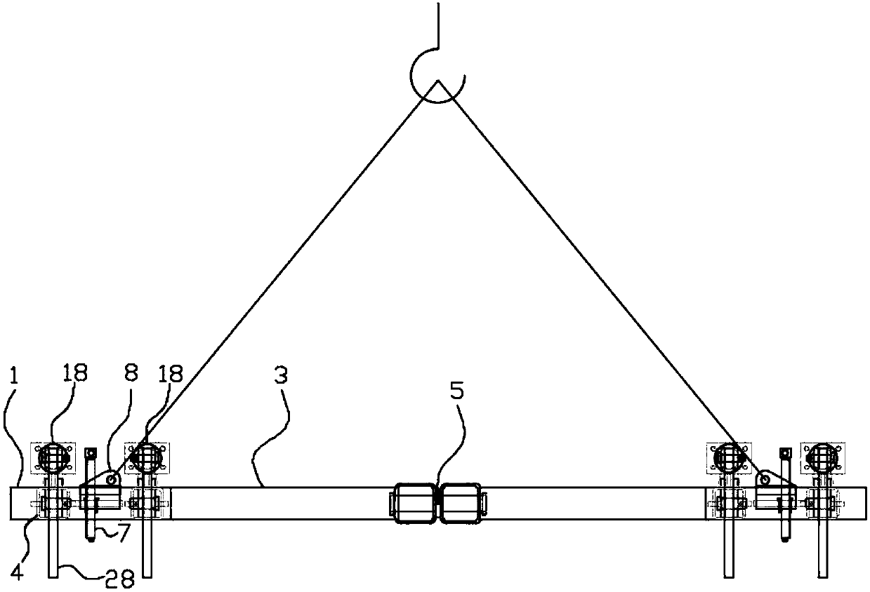
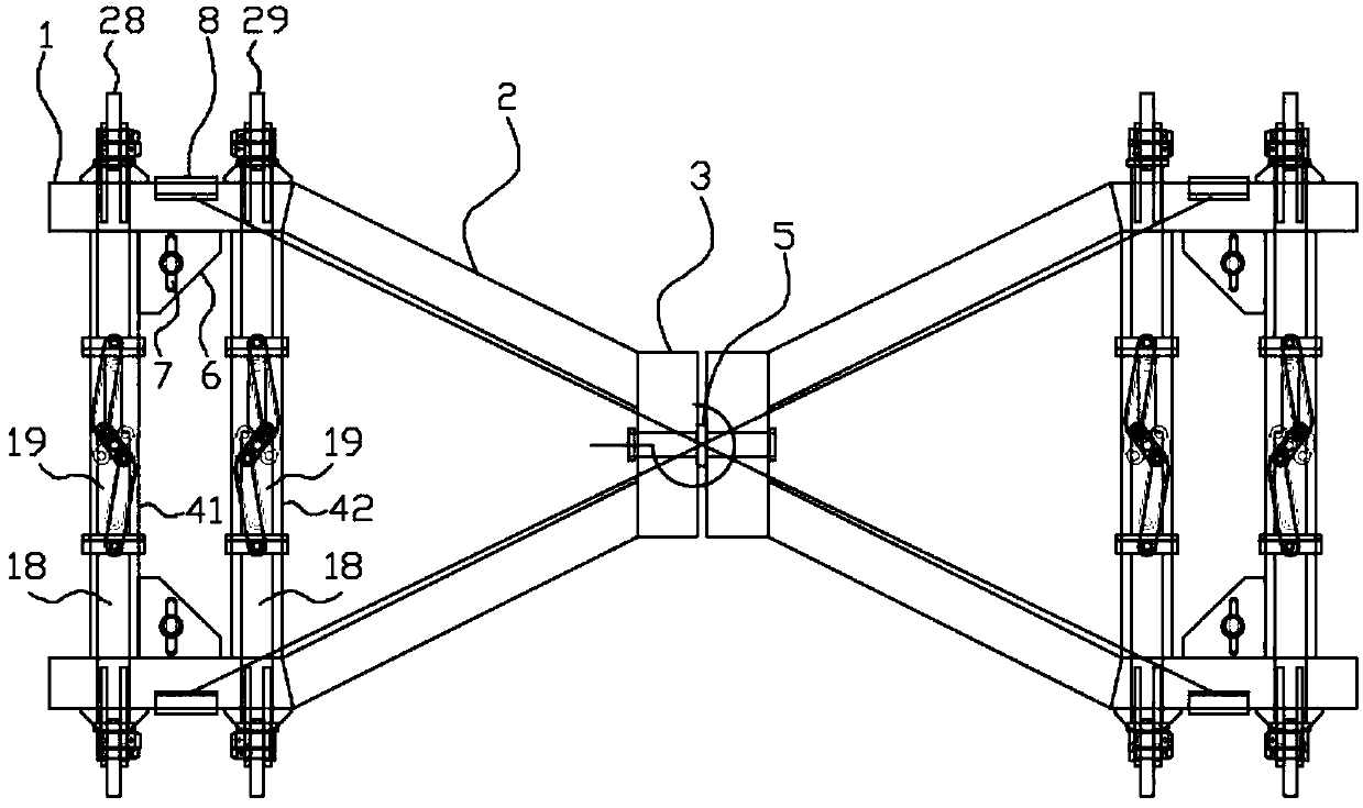
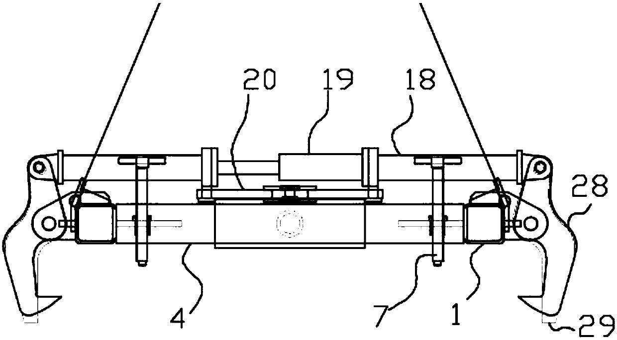
[0030] Such as Figure 1-9 As shown, the specific structure of the present invention is: a novel steel plate hanger that can accurately locate the hook, which includes two frames that are connected together and can stagger their angles through relative rotation; Beam 2, connecting beam 3 and crossbeam 4 are connected; the crossbeam 4 is composed of an outer crossbeam 41 and an inner crossbeam 42; There is a hook oil cylinder 19, and the two ends of the hook oil cylinder 19 are provided with a synchronous telescopic rod 18, and the synchronous telescopic rod 18 is hinged on the upper end of the suspens...


PUM


Abstract

The invention discloses a new type of steel plate hanger capable of accurately positioning the hook, which includes two frames connected together and capable of staggering angles through relative rotation; hook systems and steel plate hangers which are respectively provided on the frames The alignment mechanism, the height limit mechanism for adjusting the number of steel plates, the suspension rope and its connecting plate; the main frame is composed of beams, longitudinal beams, cable-stayed beams, and connecting beams, and the hook system and the steel plate alignment mechanism are arranged on the upper end of the beam; The hook system is provided with a hook, an oil cylinder, a synchronous telescopic rod and a synchronous link mechanism; the steel plate alignment mechanism is provided with an extruded plate, an oil cylinder, a synchronous telescopic rod and a synchronous link mechanism; Center of inner transoms of both frames. It can ensure that the grabbing point of the hook can still be accurately positioned when the steel plates are stacked unevenly and unevenly, and realize the stable lifting of a set number of steel plates. It has strong adaptability and simple operation.

Description

technical field [0001] The invention relates to the technical field of mechanical automation, in particular to a novel steel plate hanger capable of accurately positioning a hook. Background technique [0002] The steel plate is flat steel. During the production or use of the steel plate, it needs to be transported in batches many times. Due to the large volume and huge weight of the steel plate in batches, it cannot be transported by ordinary transport tools. The existing steel plate special-purpose spreader has a simple structure, and lifts by driving four hooks installed on the overall frame; before lifting, manual assistance is usually required to position the lifter's hooks in the gaps between the steel plates to be lifted , and then clamped by the driving mechanism of the spreader, and then lifted for transportation. Due to the misalignment of the steel plates often occurs when the steel plates are stacked, it is difficult to ensure that the stacking is neat, and this...

Claims


Application Information

Patent Timeline
Patent Type & Authority Applications(China)
IPC IPC(8): B66C1/32B66C1/14B66C1/48B66C13/08B66C13/40
CPCB66C1/32B66C1/14B66C1/48B66C13/08B66C13/40
Inventor 郑怀臣程波李骥毛成宝张维颂李佑福
Owner HUNAN WUXIN MACHINERY
Why Eureka
Try Eureka